4.18 Construction ................................................................................................. 4-15
Figures (Volume 2 – Bound Separately)
Figure 4.1 Photovoltaic Panels and Frame & String Inverters
Figure 4.2 Indicative Transformer Station
Figure 4.3 Indicative Battery Energy Storage Container
Figure 4.4 Indicative Battery Energy Storage Inverter Transformer Station
Figure 4.5 Indicative Cable Trench
Figure 4.6 Indicative MUA Substation
Figure 4.7 Indicative Switchroom and Control Centre Building
Figure 4.8 Indicative Fencing, Access Track and CCTV
Figure 4.9 Landscape Masterplan
Appendices (Volume 3 – Bound Separately)
Appendix 4.1 Glint and Glare Assessment
3210-01 / BILLOWN SOLAR FARM 4-i
4.0 SCHEME DESCRIPTION AND CONSTRUCTION METHODS
4.1 Introduction
4.1.1 This chapter of the ES provides a description of the layout and design of the various components of the Proposed Development, an explanation of the operation of the solar farm and battery energy storage facility, and details of the proposed construction methods.
4.1.2 The Applicant is proposing to construct and operate the Proposed Development for a period of 40 years, after which the Proposed Development would be decommissioned and the Site returned to its existing condition, unless planning permission is secured for continued operation.
4.1.3 As set out in the introduction to the ES the Proposed Development comprises number component parts, as follows:
• Photovoltaic Solar Panels and associated support frames
• String inverters
• Transformer Stations
• 12 No. Battery Storage Containers and associated inverter/transformers
• 1 No. Manx Utilities Authority (MUA) Substation
• 1 No. Site Substation
• 1 No. Control Centre Building / Switchroom Building
• c.1.78km of new/resurfaced internal access tracks (3m wide and constructed using compacted Type 3 stone)
• 5.7km deer/stock fencing
• c. 16 No. 3m high CCTV cameras
• c. 5 hectares of species-diverse grassland margins
• c. 65m of new native species hedgerow planting, with additional sections gapped up
• c. 0.4 hectares of native species woodland planting
4.1.4 The solar array would be capable of exporting approximately 27 MWe of renewable electricity to the local electricity distribution network, which is equivalent to the demand of approximately 7,500 homes, and circa 7% of the Island’s electricity demand.
4.1.5 The Battery Energy Storage Facility would be capable of storing 24 MW of electricity. Energy could be stored directly from the solar farm or from the grid during periods of low demand. This energy would then be available to be rapidly (within a matter of milliseconds) released back into the grid, at periods of high energy demand. Accordingly, the proposed facility assists in stabilising the capacity of the grid and supports a reliant and resilient energy supply system.
4.1.6 The system of communication between the grid and the battery energy storage system is fully automated. The facility can respond automatically to any dip in grid frequency by exporting/importing the required energy to stabilise the grid.
4.1.7 The general arrangement of the Proposed Development is shown on Figure 1.2, details of the various component parts of the Proposed Development are illustrated on the following Figures:
• Figure 4.1 Photovoltaic Panels and Frame & String Inverters
• Figure 4.2 Indicative Transformer Station
• Figure 4.3 Indicative Battery Energy Storage Container
• Figure 4.4 Indicative Battery Energy Storage Inverter Transformer Station
• Figure 4.5 Indicative Cable Trench
• Figure 4.6 Indicative MUA Substation
• Figure 4.7 Indicative Switchroom and Control Centre Building
• Figure 4.8 Indicative Fencing, Access Track and CCTV
• Figure 4.9 Landscape Masterplan
4.1.8 The following sections of this Chapter set out:
• the potential for the Proposed Development to be affected / result in Major Accidents and Emergencies;
• the impact of the project on climate and the vulnerability of the project to climate change;
• a detailed description of the project components and wastes that could arise from the development; and
• a detailed description of the construction and decommissioning methods.
4.2 Consideration of Major Accidents and Emergencies
4.2.1 Schedule 4 paragraph 8 of the EIA Regulations requires that the ES includes a description of the expected significant adverse effects of the development on the environment deriving from the vulnerability of the development to risks of major accidents and / or disasters which are relevant to the project concerned. Further, that where appropriate, this description should include measures envisaged to prevent or mitigate the significant adverse effects of such events and the approach to managing emergencies.
4.2.2 The reference to disasters is interpreted to relate to natural events, as indicated by the preamble to the 2014 Directive (2014/52/EU) which states at paragraph 15:
“In order to ensure a high level of protection of the environment, precautionary actions need to be taken for certain projects which, because of their vulnerability to major accidents, and/or natural disasters (such as flooding, sea level rise, or earthquakes) are likely to have significant adverse effects on the environment”.
4.2.3 Nonetheless, it is recognised that disasters can occur as a result of human intervention e.g., conflict and war, political influences etc.
4.2.4 In relation to major accidents the EIA Regulations refer to Directive 2012/18/EU (the control of major-accident hazards involving dangerous substances). This directive defines major accidents as:
“an occurrence such as a major emission, fire, or explosion resulting from uncontrolled developments in the course of the operation of any establishment covered by this Directive, and leading to serious danger to human health or the environment, immediate or delayed, inside or outside the establishment, and involving one or more dangerous substances”
4.2.5 The Proposed Development is located within a politically, geologically, and meteorologically stable part of Europe. Accordingly, the Proposed Development is not at material risk from, for example, civil unrest, war, earthquakes, or extreme weather conditions (hurricanes etc.).
4.2.6 In terms of any vulnerabilities specific in this location (i.e., on the Site) we note that the Site does not lie in an area prone to river or tidal flooding. The development is not considered to be vulnerable to any other potential ‘natural’ events that could result in significant environmental effects.
4.2.7 With regard to major accidents the 2014 Directive describes that:
“it is important to consider their [i.e., the Proposed Development] vulnerability (exposure and resilience) to major accidents and/or disasters, the risk of those accidents and/or disasters occurring and the implications for the likelihood of significant adverse effects on the environment.”
4.2.8 The focus here, as it is within the EIA Regulations, is on the vulnerability of the Proposed Development to major accidents and/or disasters and the likelihood of significant adverse effects occurring.
4.2.9 The solar PV panels would be inert and would not lead to any major emission, fire, or explosion. Other electrical infrastructure, in the form of inverters, transformers and cabling, would be subject to regular routine maintenance and inspection such that it will not pose a significant risk to creating an accident.
4.2.10 The Proposed Development includes a Battery Energy Storage Facility. The battery units have the potential to generate heat and therefore there is a risk of a fire development if the operator does not adopt sufficient management and control measures. As set out in detail below the Battery Energy Storage Containers would include cooling systems which are designed to regulate temperatures to within safe conditions to minimise the risk of fire. The units would also contain fire detection and suppression systems.
4.2.11 Based upon the foregoing, we concluded that the Proposed Development would not give rise to significant adverse effects on the environment deriving from the vulnerability of the development to risks of major accidents and / or disasters.
4.3 Climate Change
4.3.1 Schedule 4 of the EIA Regulations requires Environmental Statements to include:
A description of the likely significant effects of the development on the environment resulting from, inter alia:
(f) the impact of the project on climate (for example the nature and magnitude of greenhouse gas emissions) and the vulnerability of the project to climate change
4.3.2 This section of the chapter firstly considers the impact of the project on climate change and then goes on to consider the vulnerability of the project to climate change.
Impact of the Proposed Development on Climate
4.3.3 The Proposed Development would not result in any direct emissions of greenhouse gases. However, as with most new development there would be indirect emissions associated with the construction and operation of the various development components.
4.3.4 Emissions would arise from the construction of the facility through embedded carbon within construction materials, the operation of construction vehicles and non-road mobile machinery (NRMM) during the construction phases and the transport of construction materials to Site and waste away from the Site.
4.3.5 Measures would be adopted within the design of the facility to ensure where possible that sustainable construction and procurement methods are adopted. This could be achieved in a number of ways such as:
• use of prefabricated elements, that reduce waste, vehicle movements and the need for onsite construction materials;
• use of locally sourced construction materials e.g., aggregate from Billown Quarry;
• use of machinery and plant that adhere with prevailing emissions standards and which are maintained in good repair to remain fuel efficient;
• minimise disturbance to soil through careful design and constriction management; and
• reduce construction operative car use through adoption of a Construction Phase Travel Plan.
4.3.6 Minimisation of waste would also help reduce the carbon impact of construction through use of less materials, avoiding carbon emissions associated with disposal and reducing waste management HGV movements. A Site Waste Management Plan (SWMP) would be developed and implemented by the Principal Construction Contractor. The SWMP would improve waste resource efficiency, increase waste and materials awareness of staff, and highlight areas where waste management can be improved. All leading to reduced carbon impacts.
4.3.7 The operation of the development would generate renewable electricity. As set out in Chapter 1.0 virtually all of the electricity on the Isle of Man is generated from
fossil fuels, with the majority coming from Pulrose Combined Cycle Gas Turbine (CCGT). The carbon intensity of a CCGT is 0.357 kgCO2e/kWh1. Based on solar irradiance data for the latitude of the Site the solar farm is predicted to generate 28.36 GWh of electricity per year. It would therefore have the potential to directly offset 10,125 tonnes of CO2 per year, the equivalent to over 10% of the CO2 emissions associated with car usage on the Isle of Man2. Other climate change benefits derived from the development include a reduction in the intensity of agricultural practices at the Site. This has climate change benefits in terms of reduced use of fertilizer (which is a very carbon intensive material), carbon sequestration through tree and hedgerow planting and reduced soil disturbance leading to increased soil organic matter.
The Vulnerability of the Project to Climate Change
4.3.8 Changes in weather patterns resulting from climate change have the potential to impact development, requiring future development projects to consider if they would remain robust and resilient to long term changes in the climate. The Met Office has produced a series of climate predictions up to 2080 as part of the UK Climate Projections 2018 (UKCP18) project. The predictions set out a greater chance of warmer wetter winters and hotter drier summers, with higher intensity rainfall events and storms becoming more common. Increases in storm surges and sea level rise is also predicted.
4.3.9 In relation to surface water flooding and increased propensity for flooding events resulting from climate change the Proposed Development is not classed as a vulnerable development. The Site lies outside an area at risk from river and tidal flooding. Whilst parts of the site are shown to be susceptible to surface water flooding this is very localised and associated with topography. The panels are themselves not vulnerable from surface water flooding as they are raised 800 mm from ground level and cabling would not be affected. The main operational compound is not located in an area affected by surface water flooding. Nonetheless, critical infrastructure such as the transformers, battery energy storage containers, substations and control rooms would be constructed on concrete plinth foundations which would raise them above ground level and therefore reduce the impact of any localised surface water flooding.
1 Valuation of energy use and greenhouse gas. (2021) Department for Business, Energy and Industrial Strategy.
4.3.10 The development is not considered to be vulnerable to any other impacts associated with climate change.
4.4 Solar Panels & Frames
4.4.1 The Proposed Development comprises the installation of static solar PV panels mounted to a steel and aluminium frame. The panels would be tilted at a horizontal angle of approximately 30° and would face in a southerly direction at approximately 200° from north. The indicative layout of the solar panels is illustrated on Figure 1.2 and a typical solar panel frame configuration is illustrated on Figure 4.1. The lowest edge of the solar panels would be raised approximately 800 mm above ground level to enable the area under the panels to be grazed by sheep.
4.4.2 The layout, angle and tilt of the solar panels balances the highest solar efficiency from the arrangement whilst avoiding adverse impacts in relation to glint and glare. The design of the layout considers the tracking of the sun and factors such as shadowing that would result from adjacent rows of panels. The panels have been orientated 20 degrees west of due south to ensure that there are no unacceptable effects on users of Ronaldsway Airport or the operation of the air traffic control tower. The results of the glint and glare assessment are presented in Appendix 4.1.
4.4.3 The solar PV support frames would be arranged into rows set approximately 3 m apart and the maximum height of the panels along the back edge of the array would be approximately 3.5 m.
4.4.4 The solar PV support frame structures would consist of steel uprights and aluminium or steel cross bars. The steel uprights would comprise hollow 3 mm sheet steel post with a u-shaped cross section. A typical post cross section is illustrated on Figure 4.1.
4.4.5 The posts would be ram driven into the ground using a number of specialist small scale GPS controlled piling machines to a depth of approximately 1.2 m, depending on ground conditions. The rest of the support frame would then be fitted to the posts to create angled support tables ready for the solar panel installation.
4.4.6 The solar PV modules would be mounted on to the pre-constructed support frame table. The solar PV modules convert solar irradiance (sunlight) into direct current (DC) electricity. The individual solar PV modules within the Proposed Development would consist of dark blue, dark grey or black photovoltaic cells. PV technologies are developing rapidly and it is not possible to specify the precise panel type, as
this will depend on the competitive procurement process and the technology available at the time of construction.
4.4.7 The solar PV modules would be connected in strings and cabling would be secured to the rear of the solar panel and would be protected from grazing livestock by suitable trunking/elevation. From the end of each run the cables would be taken below ground and would be connected to string inverters located at the end of intermittent rows. If there are areas of archaeological sensitivity, surface mounted cable trunking would be used to avoid any impacts on buried archaeology. The string inverters would be located throughout the Proposed Development. The string inverters would in turn connect to the transformer stations which would be dispersed throughout the layout as illustrated on Figure 1.2. Ten transformer stations are proposed.
4.5 String Inverters
4.5.1 String inverters take direct current (DC), as generated by the solar panels, and convert it into alternating current (AC) to enable the on-site generated electricity to be transferred to the on-site Substation and in turn to local electricity distribution network. The design of string inverters varies between manufactures but they are typically approximately 1.0 m wide × 0.75 m high × 0.4 m deep and attach to the end of panel rows, as shown on Figure 4.1. Due to rapid advances in technology, it is not possible to specify the precise type of inverter as this will depend on the detailed electrical design and competitive procurement process. However, we suggest that the final details could be controlled through suitably worded planning conditions requiring the final details to be submitted.
4.6 Transformer Stations
4.6.1 The development requires the installation of ten transformer stations, as shown on Figure 2.1. The transformers would control and increase the voltage of the electricity generated by the solar panels before it reaches the on-site MUA Substation and distribution network. The transformer stations comprise individual steel containers (approximately 6.0 m long × 2.4 m wide × 2.9 m high). The transformer stations would be supported by strip or slab foundations depending on localised ground conditions. The maximum height, with foundations, would be no greater than 3.4 m. The transformer stations would contain the transformers necessary to connect the solar farm to the on-site MUA Substation. Each
transformer station would be finished in a green (BS Colour/RAL to be agreed through condition). Figure 4.2 illustrates the transformer station.
4.6.2 Due to rapid advances in technology, it is not possible to specify the precise type of transformer as this will depend on the detailed electrical design and competitive procurement process. However, we sugest that the final details could be controlled through suitably worded planning conditions requiring the final details to be submitted.
4.7 Operational Compound
4.7.1 The operational compound for the Proposed Development would be located centrally within the Site. The compound would provide car parking for operational staff, the Battery Energy Storage Facility, Control Room, Swithroom Building and the MUA Substation.
4.7.2 The compound would be approximately 50 m × 50 m in area. Except for the concrete foundations for the various elements of equipment, the compound would comprise crushed stone on a geomembrane so would be permeable to surface water.
4.7.3 The compound would be fenced. On the basis of the source noise levels utilised for noise assessment (Chapter 6.0) it is proposed that the fence would be 3 m in height and would be capable of providing acoustic screening. It is proposed that the details of the fencing are subject to a planning condition but are likely to comprise an acoustic timber construction, with matching gates for vehicular and staff access.
4.8 Battery Energy Storage Facility
4.8.1 The Proposed Development would comprise twelve Battery Energy Storage Containers along with associated inverters and transformers as illustrated on Figure 1.2.
4.8.2 The Battery Energy Storage System would be contained within a modified ISO shipping container as illustrated on Figure 4.3, the containers would be approximately 12.2 m long × 2.4 m wide × 2.9 m high. The footprint of each containers would be c. 30 m2 and would be supported by strip or slab foundations depending on localised ground conditions. The maximum height of the containers, with foundations, would be no greater than 3.4 m.
4.8.3 The containers would contain battery modules, two air conditioning units, a fire suppression system and a battery monitoring, management and protection system. Each container would be finished in a green (BS Colour/RAL to be agreed through condition) and would be prefabricated off-site.
4.8.4 There would be three inverter/transformer stations associated with the Battery Energy Storage Facility as illustrated on Figure 4.4. The inverters would convert the supply between the direct current (DC) from the battery and alternating current (AC) required for distribution to the local electricity distribution network. The transformer would step-up or step-down the voltage of the supply as required for transmission/storage.
4.8.5 The three inverter/transformer stations would comprise a single transformer unit approximately 3.9 m long × 3.9 m wide × 3.2 m high, with an inverter unit either side that would each be approximately 3.0 m long × 3.0 m wide × 2.9 m high. The inverter stations would be erected on concrete sleeper/skid foundations that would give them an overall height of circa 3.4 m above ground level. The inverter/transformer stations would be finished in a recessive green colour (BS Colour/RAL to be agreed through condition).
4.8.6 The Battery Energy Storage Facility would be connected to the solar panels and inverter stations and would assist in managing frequency and voltage fluctuations on the transmission network by ensuring that supply and demand in the area are balanced.
Fire Risk Management
4.8.7 Fire risk within the energy storage containers is managed in several ways, (in addition to the base chemistry of the battery cells), including software and hardware fail safes and fire suppression systems.
4.8.8 To maintain internal operating conditions, each container would include cooling units and an integral battery management and fire suppression system which includes:
• A monitoring and detection system that would shut down components in the event of elevated temperatures that could cause as fire.
• A suppression system which, in the unlikely event of a fire, acts by means of specifically designed gas (normally a blend of argon and nitrogen), widely used
in the industry, to cool and smother fire. The gas is designed not to harm human health or the environment.
4.8.9 The temperature within each cell of each battery module is monitored by the container monitoring system and any temperature variation within an individual module outside optimum operating conditions would trigger a response from the air conditioning units. If temperature increase continues or there is a failure of the airconditioning units, the container would automatically partially of fully shutdown to mitigate against the risk of thermal runaway and fire.
4.8.10 In the very unlikely event of a battery fire in one of the modules a fire suppression system would be triggered automatically. The fire suppression system would comprise FM200 gas or similar. This is a waterless fire protection system and as such there is no risk to soils or ground water as a result of operation. FM200 would be discharged into the fire risk area and would suppress any fire immediately. FM200 is a synthetic/chemical fire suppression gas and extinguishes a fire by removing the free radicals or heat elements from the fire triangle. (Oxygen, Heat and Fuel). FM200 systems are widely used for confined spaces and reach extinguishing levels in 10 seconds or less, stopping fires before they cause significant damage. FM200 extinguishes the fire quickly, which means less damage to adjacent battery modules and lower repair costs.
4.8.11 FM200 fire suppression is found as an active compound as a propellant in medical inhalers and as such it is extremely safe within the correct fire suppression design.
4.9 Electrical Cabling
4.9.1 On-site electrical cabling is required to connect the solar panels to the string inverters, to the transformer stations, to the proposed MUA Substation and the control centre. In addition, a high voltage connection to the point of connection is required, whether that is to the 33 kV OHL or Castletown Substation.
4.9.2 Figure 4.5 provides details of an indicative cable trench. Cable trenches would generally run parallel and adjacent to the on-site access tracks and fence lines. In addition to electrical cabling the trenches may also carry earthing, data and communications cables and will be backfilled with fine sand and excavated materials to the original ground level. Marker posts would be placed on either side to clearly demarcate the location of the cable crossing, if required. Cabling will also be required for power and data transfer associated with the CCTV system
described below. This will generally follow the perimeter fence lines where the CCTV cameras would be located. If there are areas of archaeological sensitivity, surface mounted cable trunking would be used.
4.10 MUA Substation
4.10.1 The MUA Substation building would be positioned close to the east of the Switchroom Building close to the potential point of grid connection on the 33 kV OHL, as illustrated on Figure 2.1.
4.10.2 The illustrative design for the MUA Substation is shown on Figure 4.6. The building would be finished in a recessive green colour (BS Colour/RAL to be agreed through condition). The final design for the substation would be subject to agreement with the MUA.
4.11 Switchroom & Control Centre Building
4.11.1 The Switchroom and Control Centre Building would be located adjacent to the MUA Substation building.
4.11.2 The Switchroom building would control the power flows from the solar array and Battery Energy Storage Facility to the MUA Substation. The Control Centre would contain equipment necessary for monitoring the performance of the solar farm and Battery Energy Storage Facility. This would not be permanently manned and would be for visiting maintenance engineers. As such welfare facilities would not be included.
4.11.3 The illustrative design for the Switchroom and Control Centre Building is shown on Figure 4.7. The building would be finished in a recessive green colour (BS Colour/RAL to be agreed through condition). The overall footprint of the Switchroom Building would be approximately 68 m2.
4.12 Access Tracks
4.12.1 Operational access to the Site would be via the existing eastern approach to Billown Mansion from the A3, Malew Road. New permanent access tracks would provide access into the solar farm from the eastern approach road.
4.12.2 The Proposed Development would require approximately 1.9 km of permanent new stone access track, approximately 3 m wide. The access tracks have been located
so they utilise existing field gates between fields to reduce the impact on hedgerows.
4.12.3 The permanent access track would be formed by excavating 200 mm and laying clean Type 3 stone within a geogrid over a geotextile membrane, depending on ground condition. The layout of the permanent access tracks is illustrated on Figure 2.1, and Figure 4.8 illustrates an indicative cross section through a typical access track construction.
4.13 Security
4.13.1 Security would be provided by approximately 2.1 m high deer/stock fencing and pole mounted CCTV cameras. The location of the fencing is illustrated on Figure 1.2 and the indicative appearance is illustrated on Figure 4.8. The CCTV poles would have a maximum height of 3 m and would generally have one pan-tilt-zoom (PTZ) camera focussed along the boundary of the Site. At certain locations two cameras would be deployed so that they can be targeted on specific locations. All cameras would operate using infra-red technology and as such no additional lighting would be required.
4.14 Drainage
4.14.1 The solar panels would allow rainwater to fall between gaps to the ground below the panels where it would percolate to ground. Erosion would be prevented by maintaining the grass sward beneath the panels that would prevent rilling.
4.14.2 All new site access tracks would be constructed of permeable stone and would infiltrate to ground. The transformer stations, Battery Energy Storage Containers, Switchroom Building, Control Centre and DNO Substation would drain to localised filter drains / stoned surrounds that would allow percolation to ground.
4.14.3 Foul water from the welfare facilities within the control room would captured in a sealed septic tank and emptied periodically by tanker.
4.15 Lighting
4.15.1 Lighting would be limited to the Switchgear Building and Control Buildings. Low level lighting would be positioned above access doors and would only be activated by passive infra-red (PIR) sensors for security/emergency purposes or when
switched on by a maintenance engineer. No areas of the Proposed Development would be continuously lit during operation.
4.16 Landscaping
4.16.1 The landscape proposals for the Site are illustrated indicatively on Figure 4.9 and would be developed in detail prior to commencement of the development.
4.16.2 The soft landscape proposals build on the existing landscape features and comprise:
• Retention of existing vegetation patterns as far as practicable by maintaining a minimum 6 m buffer between field boundary hedgerows and woodland, and the stock fencing around the development areas.
• Creation of buffer zones between fence lines and field boundaries for habitat connectivity, either seeding these areas with species-rich grassland mixes or allowing natural regeneration through a managed rewilding approach.
• Gaps in existing hedgerows would be planted up, and the hedgerows would be maintained at a height of approximately 3 m to provide enhanced visual screening.
• Planting 60 m of new native hedgerow along a currently unvegetated section of the southern boundary of the Site.
• Planting a belt of new native woodland along the eastern boundary of the Site to screen views from the property at Great Meadow, approximately 3,790 m2 in area.
• Use of Native species trees and shrubs to diversify the range of native species in the local area to reduce biosecurity threats from pests and disease.
Grid Connection
4.16.3 As set out previously the precise location and method of connection to the local electricity distribution network has yet to be agreed. However, the planning application provides for two options. Either connection into the 33 kV OHL that crosses the Site or connection to the Castletown Substation. The grid connection route is shown on Figure 1.2.
4.16.4 If connection to the Castletown Substation is selected this would require a cable trench between the on-site MUA Substation and Castletown Substation, the route of which is shown on Figure 2.1.
4.16.5 The grid connection would be located underground and there would be no above ground infrastructure required other than within the operational substation compound.
4.16.6 Rigid corrugated cable ducts would be laid within a trench excavated to a depth of approximately 1 m and to a width of approximately 0.7 m (the approximate width of an excavating bucket) using a wheeled excavator or similar. The cabling duct would be placed on a blinding layer of sand or screened earth to prevent damage from sharp objects. A further blinding layer would then be placed on the ducting. The trench would then be backfilled with the previously excavated material.
4.16.7 A working area of approximately 3 to 4 m in width would be required during the trenching and cable laying works for the operation of machinery and temporary storage of excavated material prior to backfilling.
4.17 Operations
4.17.1 Once the Proposed Development is constructed access to the Site would be limited to routine solar maintenance and landscape management operations. The Proposed Development would not be permanently staffed. Maintenance access to the Site would be by a small van or similar.
4.17.2 Should more major repairs be required, such as the replacement of transformer stations, more staff and specialist equipment (cranes and low loaders) would be required. This is not anticipated to be a regular occurrence.
4.17.3 The main operational noise would be associated with the string inverters, transformer station, and Battery Energy Storage containers. The noise impacts associated with these elements are assessed in Chapter 6.0, Noise.
4.17.4 As set out above the main activity during the operational phase of the development would be grazing of a flock of sheep below the solar panels and/or periodic mowing or other landscape maintenance. This would retain most of the Site in productive agricultural use.
4.18 Construction
4.18.1 The following section provides a summary of the key elements of the construction of the Proposed Development. This description is not intended to be prescriptive and the exact construction methods, phasing and programme would be determined
by the appointed designers and contractors. However, the following description enables the principal construction phases and methods to be understood.
Programme
4.18.2 The timing of the construction works would be dependent on the grant of planning permission for the Proposed Development, subsequent contract negotiations and prevailing weather and ground conditions.
4.18.3 The construction period is anticipated to take approximately twenty-four weeks, including testing and commissioning.
4.18.4 This construction programme would allow for the following key construction-related works to be undertaken:
• erection of Heras fencing around tree root protection areas;
• establishment of site compound;
• construction of site access tracks;
• erection of deer / stock fencing and gates to site perimeter;
• installation of solar panels and frames;
• installation of CCTV poles and cameras;
• installation of string inverters and transformer stations;
• installation of cable trenches;
• installation of Battery Energy Storage containers;
• installation of control building, switchroom building and MUA substation building;
• installation of filter drains;
• grid connection;
• cultivation and seeding; and
• hedgerow and woodland planting.
Construction Hours
4.18.5 Construction activities would take place six days per week, during the following hours:
• Monday to Saturday 07:00 – 19:00; with
• no works on Sunday’s or Bank Holidays.
Site Access and Compounds
4.18.6 Construction traffic would access the Site via the existing access to Billown Farm from the A7, Douglas Road. An existing access track runs south from the entrance for approximately 400 m where it meets the Billown Mansion Eastern Approach, at this point access is via an existing field gate into the Site.
4.18.7 A temporary compound would be created in Billown Farm yard to allow for equipment delivered on large articulated HGVs to be offloaded e.g., solar panels and supports. From here smaller low loaders or tractor and trailers would be used to transport the equipment to the main construction compound within the Site.
4.18.8 Smaller HGVs used to deliver aggregate and other general construction material would proceed directly to the main construction compound along the existing access track.
4.18.9 To minimise disturbance to residential properties the main compound is likely to be located in field no. 434048. The compound would be formed by excavating and storing topsoil, laying a permeable geomembrane and placing crushed stone. The compound would be fenced and temporary lighting provided. The panels located within the footprint of the compound would be scheduled for erection at the back end of the programme. During this period a satellite compound would be provided, potentially in the are identified for tree planting on the eastern boundary of the Site.
4.18.10 The compound would include:
• temporary offices/buildings providing office, canteen, and welfare facilities for construction operatives;
• parking areas construction workers;
• dedicated waste storage areas;
• fuel and oil chemical stores; and
• equipment and material laydown areas.
4.18.11 All construction staff would arrive and park at the main construction compound. During periods of maximum construction activity, when manpower requirements would be greatest, staff would be encouraged to car share and/or use minibuses provided by the contractor from a central pickup location away from the Site.
4.18.12 The Transport Statement submitted with the planning application concluded that the highways network is capable of accommodating the proposed construction activities without improvements, other than widening the site entrance to allow vehicles to pass.
4.18.13 At the end of the construction period the construction compound would be decommissioned. Stone and matting would be removed, and the areas would be restored to grassland.
Construction Plant
4.18.14 Plant on site is likely to comprise:
• a number of small scale mechanical pile driving rigs for frame supports
• 360° excavators;
• dumper trucks and rollers for access tracks;
• trenching machines;
• telehandlers, and
• cranes for transformers and Battery Energy Storage containers.
4.18.15 The numbers and size of this equipment will depend on the works that are being undertaken on site at a given time.
Core Construction Works
4.18.16 The main construction phases of the project are described below.
Site Preparation and Development of Construction Compounds
4.18.17 The perimeter of the construction Site would be fenced with the proposed deer/stock fencing. Temporary Heras fencing or similar would be used around compounds and other work areas until the perimeter fencing is erected and the Site secured.
4.18.18 The construction compound(s) would be created for the initial Site earthworks phase. The compound would provide temporary Site offices, welfare facilities and material and plant storage areas. Dedicated refuelling areas and chemical and oil storage areas would also be provided within the compound as required and these would be fully bunded to comply with Environment Agency requirements.
Earthworks, Foundations and Piling
Excavations
4.18.19 The topsoil excavated for the permanent access tracks and foundations for the Transformer Stations, Battery Energy Storage Containers, MUA Substation Building, Control Room and Switchroom Building would be re-used on site or stored adjacent to the excavations for use in restoration following decommissioning.
Temporary Excavations
4.18.20 Temporary excavations required for construction would be minimal and would primarily be associated with trench excavations for cable runs. Topsoil and subsoil would be stored separately immediately adjacent to the excavation in stockpiles not exceeding 1 m in height. Temporary excavations would be reinstated immediately following construction to restore the previous soil profile. Topsoil would be graded out to marry the excavations with the existing site levels and the areas would be seeded with a meadow grassland seed mix suitable for sheep grazing as detailed above.
Foundations
4.18.21 The foundations for the Transformer Stations, MUA Substation, Control Room and Switchroom Building would be slab foundations or concrete sleepers, depending on ground conditions.
4.18.22 Foundation slabs and sleepers would be cast in-situ and concrete would be delivered directly to the Site via concrete mixer lorry.
Piling
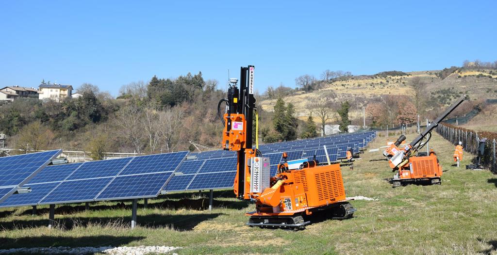
4.18.23 As set out above the support posts for the solar panel frame would be ram driven into the ground using a number of specialist small scale GPS controlled piling machines to a depth of approximately 1.2 m depending on ground conditions. A typical small scale piling machine used for solar farm construction is illustrated in the image below.
Plate 4.1: Typical GPS Solar Farm Pile Driver
Construction Lighting
4.18.24 Lighting during construction would need to be sufficient to satisfy health and safety requirements, whilst ensuring impacts on the surrounding environment, including from sky glow, glare and light spillage, are minimised.
4.18.25 Artificial lighting would only be used during the hours of darkness, low levels of natural light or during specific construction tasks to ensure the health, safety and welfare of those on site, including construction staff and visitors.
4.18.26 Appropriate lighting would be installed and operated to ensure that:
• access/egress points are clearly visible during operational hours;
• staff and visitors can move safely around site;
• site security can be monitored and maintained; and
• sufficient area lighting is provided for the Site office and laydown areas.
4.18.27 This would involve the use of mobile task lighting to provide the lighting necessary to satisfy Health and Safety requirements. Mobile lighting would be mounted on telescopic poles.
Construction Environmental Management Plan (CEMP)
4.18.28 A CEMP would be developed for the construction phase of the development. This is likely to comprise an overarching CEMP framework to be applied to all phases of the development and also a series of phase specific CEMP documents which
define specific measures to be adopted during the construction of the various components of the scheme.
4.18.29 The purpose of the overall CEMP would be to manage and report environmental effects of the project during construction. The CEMP would set out how environmental issues would be managed in accordance with relevant legislation, regulations and best practice guidance. It would be the responsibility of the main contractor to develop and enforce the CEMP. It is suggested that the requirement for a CEMP to be prepared is subject to a planning condition once the detailed design is completed to allow main contractor input.
4.18.30 The objectives of the CEMP would be to:
• highlight environmental impacts resulting from the development and identify sensitive receptors within the development site to the construction team;
• reduce and manage environmental impacts through appropriate construction methods;
• reduce and manage environmental impacts through implementing environmental best practice during the construction period;
• undertake ongoing monitoring and assessment during construction to ensure environmental objectives are achieved;
• provide emergency procedures to protect against environmental damage;
• provide an environmental management structure for the construction stage;
• recommend mechanisms to reduce risks of environmental damage occurring; and
• ensure procedures are in place for consultation with EA, Natural England, Local Authority Officers and other stakeholders throughout the works if necessary.
4.18.31 A CEMP for a project of this nature would typically cover the following key elements:
• drainage, water quality and hydrology;
• dust, emissions and odours;
• health and safety/site management;
• waste management;
• traffic management;
• wildlife and natural features; and
• contaminated material.
4.18.32 Prior to the commencement of construction works an environmental walkover would be undertaken to establish any changes in the environmental baseline since the surveys undertaken as part of the EIA and planning submission. This walkover would be used to update any of the defined construction procedures as necessary.
4.18.33 The main contractor would also develop a local community liaison strategy. This strategy would detail how the contractor would engage with the local community to inform them of the construction progress and inform them of any works that may give rise to queries or concerns. The strategy would also set out the means to allow the public to raise any concerns with the contractor and mechanisms to resolve any complaints.
4.18.34 The main contractor would take regard of the following guidelines in preparation of the CEMP and during the operation of the Site:
• Environment Agency. Pollution Prevention Guidelines 1: General Guide to the Prevention of Pollution (PPG1)
• CIRIA. Control of water pollution from construction sites C532 (2001)
• CIRIA. Environmental Good Practice on Site C650 (2005)
Decommissioning
4.18.35 At the end of the Solar Farm’s 40-year life the Proposed Development would be decommissioned and the Site would be returned to solely agricultural use. Decommissioning would require similar plant to the construction phase and would result in very similar traffic impacts.
4.18.36 All above and below ground infrastructure would be removed from Site and would be recycled, if possible. Following decommissioning at the end of the schemes operational life or when panels need to be replaced due to failures/damage solid waste will be created. PV panels comprise a high proportion of glass along with smaller amounts of aluminium and other metals. All of these components are readily recyclable. As the solar industry expands the recycling market is following. There are an increasing number of specialist recycling firms that are developing technologies to allow the photovoltaic cells to be more easily recycled, enabling an even greater proportion of the solar panels to be recycled. In addition, support frames, fencing, CCTV poles and cabling all contain recyclable materials and stone/concrete can be processed for use as secondary aggregate.
4.18.37 Solid waste generated by decommissioning works can therefore be effectively managed by moving waste up the waste hierarchy through recycling for beneficial use. As such significant effects associated with disposal of waste as a result of the Proposed Development would not occur.
Copyright in submitted documents remains with their authors. Request removal