Loading document...
During the course of the study, a preconstruction SREM assessment was performed for the dwelling. The SREM calculations determine the overall amount of energy required for the development and accordingly quantify the amount of renewable energy required for the entire site based on the selection of renewable systems.
To achieve compliance with Part 1 of the building regulations, in particular in relation to the renewable energy supply, the following renewable technologies were selected:
Although the building will be primarily utilized by Solar Panels and Ground Source Heat Pump, yet the overall average renewable contribution equates to 4,083 kWh/m²/year.
The new Building Regulations Part 1 provides a dramatic improvement in energy efficient standards in homes.
The aim of Part 1 of the Second Schedule to the Building Regulations is to limit the use of fossil fuel energy and related CO₂ emissions arising from the operation of buildings, while ensuring that occupants can achieve adequate levels of lighting and thermal comfort.
This revision of Part 1 represents a significant step towards the optimization of the efficiency of energy use in new dwellings and the minimization of related CO₂ emissions. It is intended that the standards specified here will be tightened further at the next review. The aim is to achieve zero carbon emissions associated with the operation and use of dwellings, at the earliest date practicable.
The following represents a reasonable minimum level of energy provision from renewable energy technologies in order to satisfy the new regulations:
"Renewable energy technologies" means technology, products, or equipment that supply energy derived from renewable energy sources, e.g., solar thermal systems, solar photo-voltaic systems, biomass systems, systems using biofuels, heat pumps, aerogenerators, and other small-scale renewable systems.
In the case of systems based on biofuels or biomass, appliances must be designed to run on these fuels only, i.e., incapable of providing thermal energy from fossil fuels, to be accepted as renewable technology for the purposes of this regulation. For example, a boiler, which could operate on either oil or a biofuel mixture, would not be considered to be a renewable technology. Therefore, this was not considered on this development.
The use of centralized renewable energy sources contributing to a heating distribution system serving all dwelling units in a development or part of a development, e.g., an apartment block, may prove to be more practicable than providing separate renewable energy for each dwelling individually. The above solution could not be applied on this standalone development.
As an alternative to providing thermal energy or electrical energy from renewable technology sources, the use of a small-scale combined heat and power (CHP) system, which contributes to the space, and water heating energy use would be acceptable. This approach may be appropriate in some high-density developments, e.g., apartment and mixed-use developments. But sadly, cannot be applied to this development.
110478 Ashdown House Planning, Hemp House, February 2013
120478 Ashdown House Planning, Hemp House, February 2013
7.0 Results
Baraweide Content By System Type Site Mide Percentage Provided And KWh/(m2/Year Of Baraweide Energy {{table:371516}} LIGHTS Adhesive Unions Plumbing. Long-term Relevance 2011
22
22
Project name
As designed
Date: Fri-Feb 24 10:02:57 2012
Address: Baraweide Street, Baraweide Road, Saxton, Isle of Man, SW1 8JY
Calculation engine: E&EN Calculation engine version: v4.1.0.0 Interface to calculation engine: ISBEA Interface to calculation engine revision: v4.1.0 BRUKL compliance check version: v4.1.0.0
Name: Dway And Walker Telephone number: 02073898890 Address: 28 A Darganche Road, Samna Court, London, SW1EJ
| Without Renewable, (LTHW oil first boiler) KWh/(m2/yr) | With Solar Panels KWh/(m2/year) | With Solar Panel and Ground Source Heat Pump with 90% input from secondary heating plant | |
|---|---|---|---|
| Total Site KW/(m2/year Usage for Space Heating And 104W | 270.97 | 4.08 | 87.04 |
| 1.1 | CO2 emission rate from the national building, kgCO2/m² annum | 72.6 |
| 1.2 | Target CO2 emission rate (TDR), kgCO2/m² annum | 72.6 |
| 1.3 | Building CO2 emission rate (BER), kgCO2/m² annum | 75 |
| 1.4 | Are emissions from the building less than or equal to the target? | BER → TDR |
| 1.5 | Are as built details the same as used in the BER calculations? | Separate submission |
Does not include a water and gas control system. Does not include a water and gas control system. Water and gas control system is not available in the U.S. and is not available in the U.S.
Approved in these checks by the unit team on supply to include water service drinking detected in similar to that for windows. Wastey windows and similar glazing are extended from the U-stock doors. *No "other" roof ventilation (no "shade works") or watering post-stock are installed or removed against the limiting standards by the unit.
| Element | Stores | Stores | Stores | Surface where the maximum value occurs* |
|---|---|---|---|---|
| Heat** | 0.25 | 0.18 | 0.3 | Zone 5/4 |
| Flare | 0.25 | 0.12 | 0.14 | Zone 5/4 |
| Roof | 0.25 | 0.18 | 0.16 | Zone 9/4 |
| Windows*** / net* windows, and midlights | 2.2 | 1.5 | 1.0 | Zone Hw/g |
| Panoramic doors | 2.2 | 1.02 | 1.5 | 64 |
| Volatile access & similar large doors | 1.5 | - | - | *No heat loss vehicle access doors* |
| High usage entrance doors | 1.5 | - | - | *No heat loss high usage entrance doors* |
Page 1 of 7
| Air Permeability | Worst acceptable standard | Flux building |
|---|---|---|
| or/(lb air) at 60 Pa | 10 | 0 |
| Zone | Bator gain limit exceeded? (%) | Internal blinds used? |
| Zone Q | N/A | N/A |
| Zone F | N/A | N/A |
| Zone H | N03 (75.4%) | ND |
| Zone M | N03 (49.3%) | ND |
| Zone R | N/A | N/A |
| Zone P | N03 (44.6%) | ND |
| Zone O | N03 (48.6%) | ND |
| Zone M | N03 (41%) | ND |
| Zone T | N03 (58.2%) | ND |
| Zone U | N03 (58.2%) | ND |
| Zone V | N03 (63.8%) | ND |
| Zone D | N03 (100.7%) | ND |
The building services parameters listed below are expected to be checked by the BGG against guidance. No automatic checking is performed by the tool.
| Whole building lighting automatic monitoring & targeting with alarms for out-of-range values | YES |
| Whole building electric power factor addressed by power factor correction | +0.95 |
Automatic monitoring & targeting with alarms for out-of-range values for this HVAC system YES
| Heating seasonal efficiency | Cooling nominal efficiency | SFP [W(2/s)] | HR seasonal efficiency |
| 2.38 | - | - | - |
Automatic monitoring & targeting with alarms for out-of-range values for this HVAC system NO
| Heating seasonal efficiency | Cooling nominal efficiency | SFP [W(2/s)] | HR seasonal efficiency |
| 2.38 | - | - | - |
Automatic monitoring & targeting with alarms for out-of-range values for this HVAC system YES
| Heating seasonal efficiency | Cooling nominal efficiency | SFP [W(2/s)] | HR seasonal efficiency |
| 2.45 | 2.5 | 3 | 3.83 |
Automatic monitoring & targeting with alarms for out-of-range values for this HVAC system NO
{{table:371531}} Local mechanical ventilation and exhaust {{table:371532}} General lighting and display lighting {{table:371533}} General lighting and display lighting {{table:371534}}
| Zone | General lighting [W] | Display temps efficacy [m/W] |
| Zone A | 50 | - |
| Zone B | 40 | - |
| Zone H | 320 | - |
| Zone M | 200 | - |
| Zone N | 70 | - |
| Zone A | 100 | - |
| Zone P | 40 | - |
| Zone G | 90 | - |
| Zone G Eroute | 30 | - |
| Zone P Eroute | 20 | - |
| Zone R | 50 | - |
| Zone R Eroute | 40 | - |
| Zone S | 30 | - |
| Zone T | 40 | - |
| Zone T Eroute | 30 | - |
| Zone U | 60 | - |
| Zone U Eroute | 40 | - |
| Zone V | 100 | - |
| Zone I | 360 | - |
| Zone L | 140 | - |
| Zone W | 130 | - |
| Zone D | 720 | - |
Separate submission
Separate submission
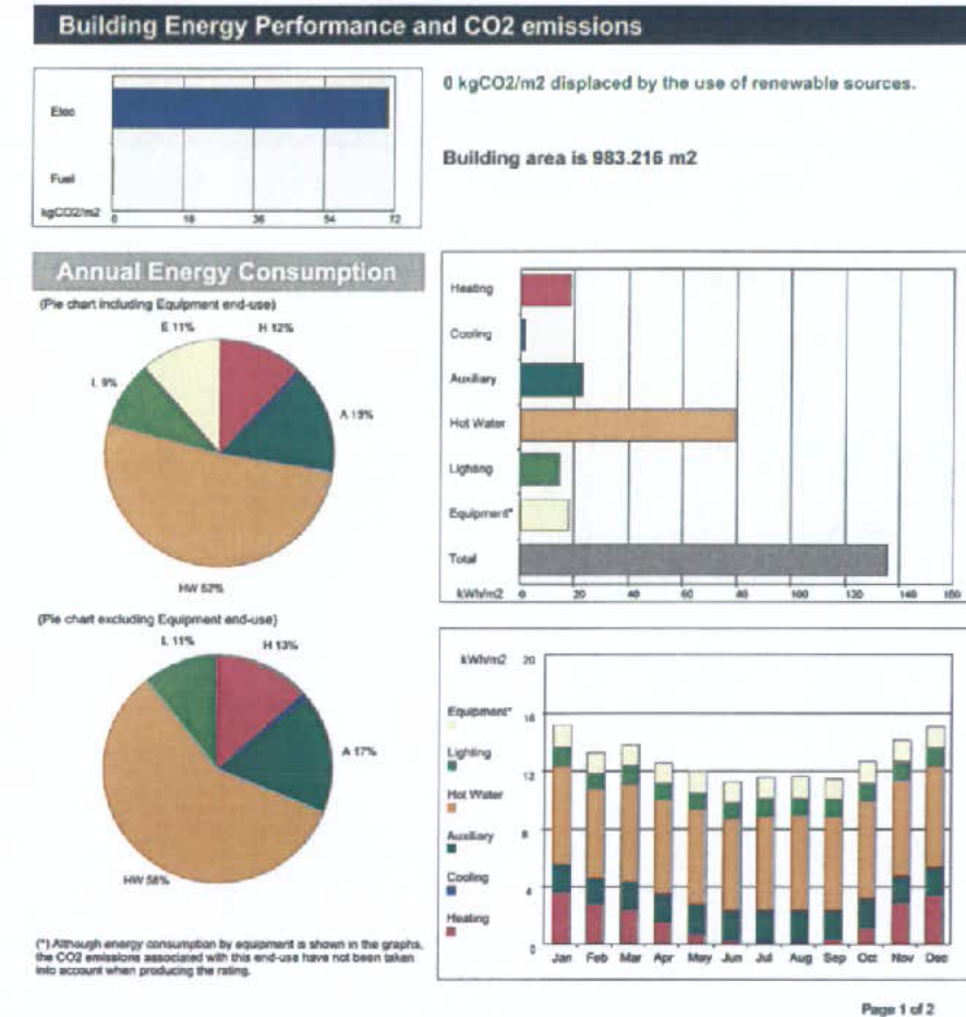
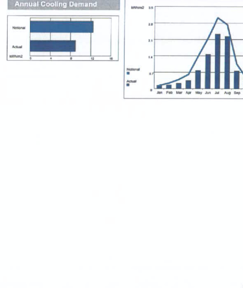
Technical Data Sheet (Actual vs. National Building) Energy Consumption by First Use (kWh/m²) {{table:371537}} *Area with capital use data Energy Production by Technology (kWh/m²) {{table:371538}} Energy & CO₂ Emissions Summary {{table:371539}}
Page 6 of 7
Page 7 of 7
Page 8 of 7
Page 9 of 7
The BCO can give particular attention to items with specifications that are better than typically expected.
Building Intro:
| Actual | Indicative Target | |
| Heating + cooling demand [NJ/m²] | 199.84 | 231.10 |
| Total consumption [kWh/m²] | 132.36 | 143.67 |
| Total emissions [kg/m²] | 70 | 72.6 |
| Element | No. | Size | Surface where the minimum value occurs* |
| Wall | 0.25 | 0.13 | Zone 00s |
| Floor | 0.2 | 0.1 | Zone 00' |
| Roof | 0.12 | 0.10 | Zone 00's |
| Windows, roof windows, and rooftops | 1.5 | 1.5 | Zone Holog |
| Parasitical doors | 1.5 | - | <1 |
| Vehicle access & similar large doors | 1.5 | - | "No heat loss vehicle access doors" |
| High usage entrance doors | 1.5 | - | "No heat loss high usage entrance doors" |
| *In p = Typical individual element U-values [N/m²K] *In m = Minimum individual element U-values [N/m²K] *There might be more than one surface where the minimum U-value occurs. |
| Air Permeability | Typical value | This building |
| m³/(L·m²·s) Gt Pa | 0 | 0 |
In this section of the report we outline the various options regarding the sustainable solutions, which were considered while compiling this report.
Solar water heating systems gather energy radiated by the sun and convert it into useful heat in the form of hot water. The energy is provided by both direct sunlight and indirect sunlight and therefore when the sky is overcast the solar panel is still converting energy into hot water. A pump is used to transfer the heat generated within the panel to a dual coil hot water storage cylinder. This hot water is stored and is available when required. A solar water heating system works alongside conventional water heating systems to ensure year-round hot water.
{{image:43464}} Figure 8.1: Solar Water Heating System {{image:43466}} Figure 8.2: Solar Water Heating System {{image:43467}} Figure 8.3: Solar Water Heating System {{image:43468}} Figure 8.4: Solar Heating System {{image:43469}} Figure 8.5: Solar Heating System {{image:43470}} Figure 8.6: Solar Heating System {{image:43471}} Figure 8.7: Solar Heating System {{image:43472}} Figure 8.8: Solar Heating System {{image:43473}} Figure 8.9: Solar Heating System {{image:43474}} Figure 8.10: Solar Heating System {{image:43475}} Figure 8.11: Solar Heating System
As illustrated in Figure 1, the solar circuit in any solar water heating system is connected to the lower coil in a dual coil solar cylinder. The panel heats the cooler water in the bottom of the cylinder. As the water increases in temperature it expands and rises to the top of the cylinder. The secondary heat source, often a boiler, is connected to the top coil in the cylinder, which ensures year round hot water. It is estimated on average that a solar water heating system can provide up to 80-83% of the annual hot water requirements of a household.
A solar controller is required with all solar water heating systems to ensure the regulation and the safety of the system. A minimum of two thermostats is required which are wired back to the controller. One thermostat is placed in a slot on the solar panel and the second thermostat is positioned in the dual coil solar cylinder. The pump is controlled by the controller. The controller prevents the pump from running if the temperature difference between the panel and the cylinder is less than approximately 6°C. This ensures that the panel will not cool the cylinder during night hours when the panel may be cooler than the temperature of water in the cylinder. The solar controller also prevents the solar panel increasing the temperature of the cylinder above 60°C.
A flat plate solar collector consists of a metal box with a glass or plastic cover and a dark- coloured absorber plate located on the bottom of the box. The box is insulated to minimize heat losses. Sunlight/radiation passes through the glass cover similar to the evacuated tubes with minimal reflection. The plate within the panel absorbs approximately 500kW/hr/hr²/yr of the suns radiation and converts it into heat. Unlike the evacuated tubes the heat is transferred to a coil within the collector as illustrated in Figure 4. The coil transfers heat directly from the panel to a dual coil hot water cylinder.
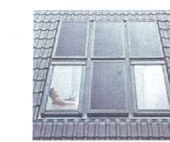
Flat plate solar panels can either be mounted proud on a roof or can be integrated into the structure of the roof as illustrated in Figure 5.
Figure 5 – Flat Plate Technology
The flat plate solar panels can either be mounted proud on a roof or can be integrated into the structure of the roof as illustrated in Figure 5.
Figure 6 – Stuck Diagram of Solid-Connected Pit System
A photovoltaic solar system must produce enough energy to power the DC inverter controller and therefore a minimum peak load of approximately 1kW which produces 1000kWh of electricity which will satisfy building Regulation Part 1 renewable energy requirements for any dwelling up to 230m².
PV solar panels can be integrated into the structure of a roof, mounted on a finished roof or mounted on A frames on flat roofs. Solar PV panels require the routing of cables from the panel to the inverter controller. They do not require any additional plumbing or maintenance as associated with the solar water heating systems.
However in this instance the size and scale of panels required is deemed impractical.
120V/50 Aishdown House Planning, Vangchown February 2012
130V/50 Aishdown House Planning, Vangchown February 2012
14
110V/50 Aishdown House Planning, Vangchown February 2012
15
16
17
18
19
1000/6/DS/01
ASHOWNE HOUSE
Richmond Square
RU 60-0015
1000/6/DS/01
1100/6/DS/01
120V/50 Aishdown House Planning, Vangchown February 2012
Biomass or wood fuel technology is one of the major growth industries in the UK and Ireland today with a huge demand for alternatives to fossil fuel. Fossil fuel substitution will only gather momentum in 40M over the coming years, only this month the energy regulator has approved a 35% rise in the cost of natural gas and oil.
UK imports 50% of the above requirement for fossil fuel; this puts the UK at significant risk in terms of securing long-term supply. Biomass that is a 'Carbon Neutral' fuel is well established and in daily use by our European neighbours. The use of biomass fuel is generally available in two forms, wood chip and wood pellet. There are a number of factors to be considered when deciding on a fuel source. There is a significant difference between the cost of wood chips and wood pellets. This is attributed to the high cost of producing the pellets and the plant required for the process.
Biomass is the ideal energy source for reducing the carbon emissions from a residential development however on the island the supply chain for fuel is still to be developed as a robust alternative energy. On these grounds this was not considered.
Building Regulation Part 1 states that excessive heat losses through the building envelope should be avoided. The thermal efficiency of a dwelling is increased by introducing better insulation, double glazing and draft proofing. The thermal efficiency of the building increases as the air permeability of the building is reduced. Ventilation is therefore required to prevent a build up of water vapour and scale air within a dwelling, which is harmful to humans and can lead to the decay of internal decoration and fabrics.
There are a number of ventilation solutions for domestic dwellings, which are discussed below.
138478 Ashdown House Planning, Grang Nown February 2012
17
138479 Ashdown House Planning, Grang Nown February 2012
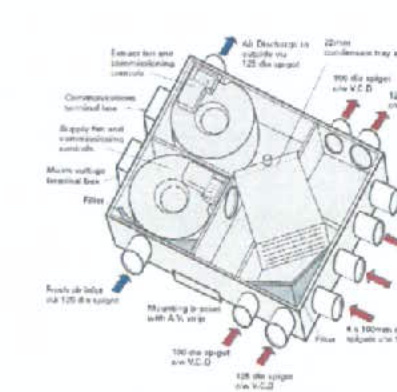
Mechanical ventilation with heat recovery is a fan driven ventilation system, which provides fresh air and also extracts exhaust air from a dwelling. Heat Recovery Ventilation units utilise energy efficient heat exchangers to transfer heat from outgoing state air to incoming fresh air, greatly reducing the energy required to maintain a constant room temperature. MVHR ensures that there is no cross-contamination, as the two air streams do not mix. The efficiency of the heat recovery system is determined by the efficiency of the heat exchanger and the fan motors within the system.
Figure 8 – Mechanical Ventilation Heat Recovery System
A mechanical ventilation heat recovery unit can be located in a cabinet in the living space or in a ceiling void. Currently these are not specified but may be considered in the post area to further reduce the energy foot print.
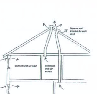
Passive Ventilation provides a natural energy-free alternative to mechanical fans and heat recovery systems. Driven primarily by the natural stack effect by which warm air rises.
Moisture-laden air is extracted directly from wet rooms through ducting up to a roof terminal where it is vented to the outside. The air within a dwelling is usually warmer than the ambient temperature and therefore rises up the duct by natural convection, carrying moisture with it as illustrated in Figure 10.
Figure 10 – Passive Ventilation System
Within a passive ventilation system windows with vents are installed which introduce fresh air into a dwelling as required. Passive ventilation systems can be controlled by humidity sensors linked to the windows and grilles. As the occupancy within a room increases, so does the humidity level. A sensor automatically adjusts the grills to extract where needed.
We propose to utilise the above principle on this development.
138476 Ashdown House Planning, Grang Nown February 2012
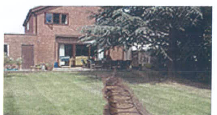
Ground source heat pumps use pipes which are buried in the garden to extract heat from the ground. This heat can then be used to heat radiators, underfloor or warm air heating systems and hot water. A ground source heat pump circulates a mixture of water and antifreeze around a loop of pipe—coiled a ground loop heat from the ground is absorbed into the fluid and then passes through a heat exchanger into the heat pump. The ground stays at a fairly constant temperature under the surface, so the heat pump can be used throughout the year—even in the middle of winter. The length of the ground loop depends on the size of the premises and the amount of heat required. Larger loops can draw more heat from the ground, but need more space to be buried in. If space is limited, a vertical borehole can be drilled as an alternative.
Some of the benefits of ground source heat pumps are:
LUMPS Ashdown House Planning, Energy Report, February 2012
Unlike gas and oil boilers, heat pumps deliver heat at lower temperatures over much longer periods. During the winter, they may need to be on constantly to heat your home efficiently. Ground source heat pumps are best suitable if the garden is suitable for a ground loop. It doesn't have to be particularly big, but the ground needs to be suitable for digging a trench or a borehole and accessible to digging machinery. Ground source heat pumps perform better with underfloor heating systems or warm air heating than with radiator-based systems because of the lower water temperatures required.
Wind turbines are vastly expanding in the services industry due to recent surge in small scale projects which includes domestic dwellings and medium scale industries. Wind turbines harness the power of the wind and use it to generate electricity. Forty percent of all the wind energy in Europe leaves over the UK, making it an ideal country for domestic turbines (known as 'microwind' or 'small-wind' turbines). A typical system in an exposed site could easily generate more power for your lights and electrical appliances.
Some of the benefits of wind turbines are:
The maintenance checks on wind turbines are required every few years and are generally cost-effective depending on the size of the turbine. A well-maintained turbine can last for more than 20 years.
LUMPS Ashdown House Planning, Energy Report, February 2012
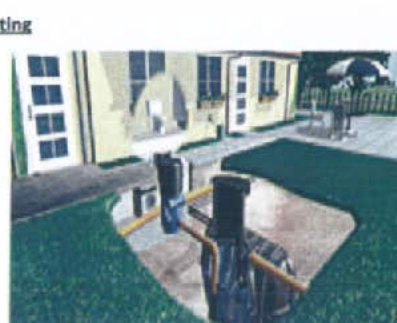
Rainwater harvesting system collects rainwater from the roof via the downpipes. It is then passed through filtration systems and stored for non-potable use which includes flushing toilets, providing water to washing machines, garden hoses, cleaning the cars, and other applications. The storage tanks are usually buried in the ground for anti-freeze protection but can also be located internally in a protective environment.
Copyright in submitted documents remains with their authors. Request removal
View as Markdown