Loading document...
MICROGENERATION INSTALLATION STANDARD: MCS 020
MCSPlanning Standards for Permitted Development Installat
TABLE OF CONTENTS 1.INTRODUCTION.............................................................................................................................................42.MCS PLANNING ST
1. INTRODUCTION1.1 This document sets out the MCS Planning Standard which must be complied with for domestic installations of It is designed to allow MCS Contractors to establish clearly whether an installation will comply with the MCS Plan Compliance with the MCS Planning Standard on its own does not bestow permitted development rights –ther MCS Contractors shall be under a duty to ensure compliance with the MCS Planning Standard in relation to any Section 2 of this document outlines the MCS Planning Standard for the installation of a wind turbine. Section 3 o MCS Certification Bodies shall be able to limit the scope of an MCS Contractor’s certification against this standa
2. MCS PLANNING STANDARD FOR WIND TURBINES 2.1 The MCS Planning Standard for wind turbines is as follows: (a) The wind turbine product shall be certificated The wind turbine calculation procedure is set out in Table 1 of this section. MCS Contractors must complete this t MCS Contractors must insert their results in the ‘results/notes’ column for each step of the calculation procedu Explanation of the calculation procedure is supported by a worked example which is in italics at the end of each 1The Microgeneration Certification Scheme standard MCS 006 –Issue 2.1.Prod
•
•
•
StepInstructionsMCScontractor results / notes1. Obtain the Ordinance Survey grid reference for the location of the proposed turbine. Eight character grid refere Use the DECC wind speed database to obtain wind data at 10metres above ground level. See ‘Note 1:DECC wi Calculate the wind speed using the following calculation (rounding to two decimal places). See ‘Note 2:1.72 Fi Calculate the rotor centre (hub) height of the wind turbine. See ‘Note 3:Rotor centre (hub) height’Example: T
5. Calculate the wind speed at the rotor centre (hub) height using the following calculation (rounding to one decima Draw a horizontal line from (STEP 5 RESULT) on the ‘wind speed (m/s) at hub’ side of the noise map to where th Is the result from STEP 6 lower than the slant distance to the nearest assessment position?If YES -the wind t
NOTE 1: DECC WIND SPEED DATABASE (STEP 1 AND STEP 2)The Department of Energy and Climate Chang
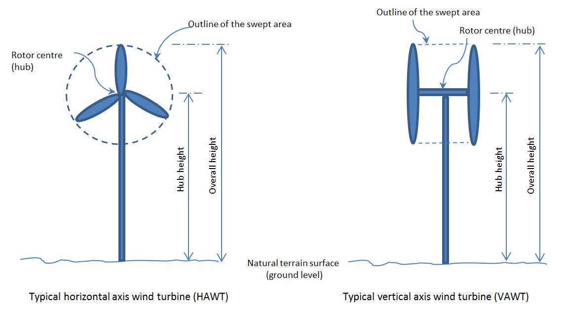
NOTE 3: ROTOR CENTRE (HUB) HEIGHT (STEP 4)The rotor centre (hub) height will be the vertical distance
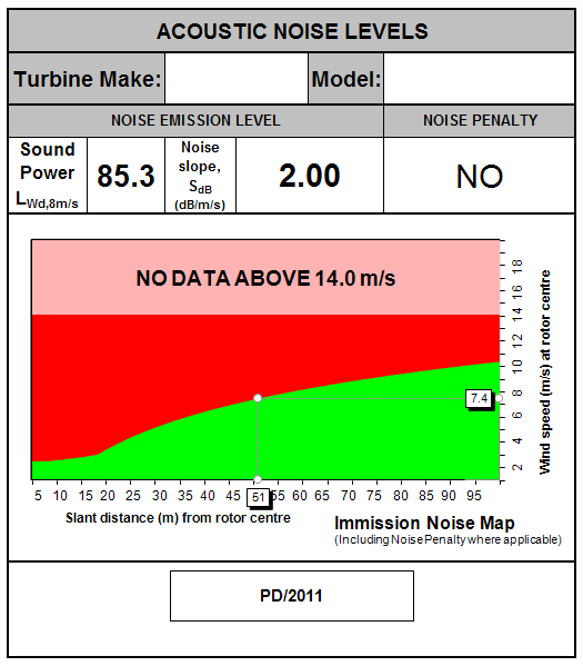
this point to the bottom of the map will give the maximum slant distance in metres from rotor centre (hub) at which
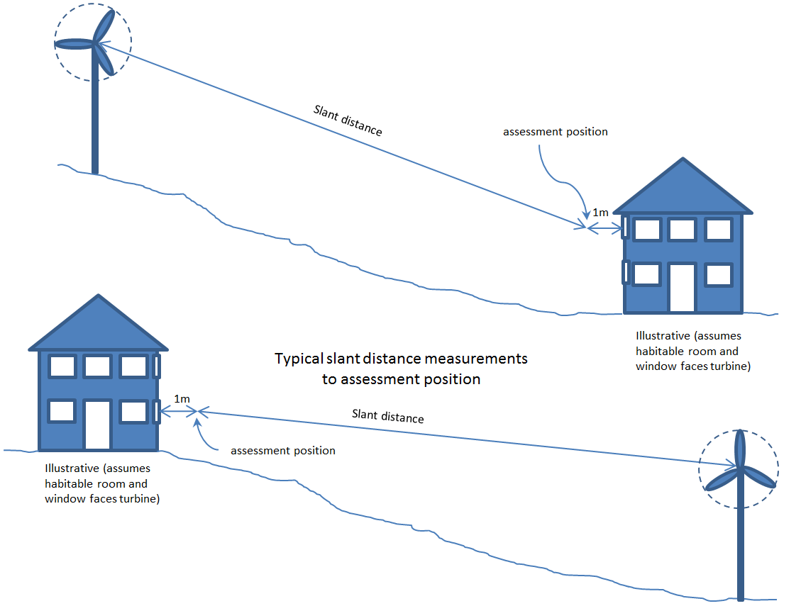
NOTE 5: SLANT DISTANCE The slant distance is measured by drawing a straight line on a 1:500 scaled elevation
3. MCS PLANNING STANDARD FOR AIR SOURCE HEAT PU The MCS Planning Standard for air source heat pumps is as follows: (a) The air source heat pump product shall be certificated in accordance with MCS 0073;(b) The air source heat pump shall be installed by an MCS Contractor in accordance with MIS 30054; and(c The air source heat pump calculation procedure is set out in Table 2. MCS Contractors must complete one table MCS Contractors must insert their results in the ‘results/notes’ column for each step of the calculation procedur Explanation of the calculation procedure is supported by a worked example which is in italics at the end of each s 3The Microgeneration Certification Scheme Standard MCS 007 –Issue 4.0.Prod
| •<br><br>•<br><br>•<br><br> | |
|---|---|
| Proposed ASHP install at 4 Milner Terrace<br><br>AP1 ground floor rear door at 3 Milner Terrace, 2m from proposed ASHP.<br>AP2 bathroom window at 3 Milner Terrace, 3.4m from proposed ASHP.<br>AP3 bedroom window at 3 Milner Terrace, 6.2m from proposed ASHP<br>AP4 bedroom window at property accross road, 10.3m from proposed ASHP<br> | |
| --- |
| 58dB(A) | ||
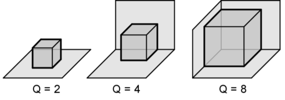
| ----------- | Q4 | |
| AP1; 2m<br>AP2; 3.4m<br>AP3; 6.2m<br>AP4; 10.3m<br> | ||
| AP1 -11 dB<br>AP2 -14 dB<br>AP3 -20 dB<br>AP4 - 25 dB<br> |
| There is a 2m high stone wall between the HP and assessmemnt positions which completely obscures AP's 1&2. No reduction is avaiable for AP's 3&4 | AP1; -10<br>AP2; -10<br>AP3; 0<br>AP4; 0<br> | |
|---|---|---|
| AP1; 58+(-11)+(-10)= 37<br>AP2; 58+(-14)+(-10)= 34<br>AP3; 58+(-20)+0= 38<br>AP4; 58+(-25)+0= 33<br> | ||
| 40 | ||
| AP1 40-37= 3dB<br>AP2 40-34 = 6dB<br>AP3 40-38 = 2dB<br>AP4 40-33= 7dB<br> |
| AP1; 40+1.8= 42 PASS<br>AP2; 40+1= 41 PASS<br>AP3; 40+2.1= 43 FAIL<br>AP4; 40+0.8= 40.8= 41 PASS<br> | ||
| AP1 -11dB<br>AP2 -14 dB<br>AP3 -20dB<br>AP4 - 25 dB<br><br><br>Fail by 0.1dB<br><br>------ |
•
•
•
•
•
•
•
NOTE 7: DECIBEL CORRECTION (STEP 9)Please note that the left hand column should be used for both pos
4. GLOSSARY OF TERMSAglAbove ground level.AttenuationReduction in the intensity o
RotorRotating part of a machine e.g. a wind turbine.Rotor centreThe geometric centre of the swept area of the w
AMENDMENTS ISSUED SINCE PUBLICATION Document numberAmendment detailsDate1.0First Issue19/08/20111.1Clarification to Step 10 under Air S
Copyright in submitted documents remains with their authors. Request removal
View as Markdown