**Document:** Tower of Refuge Lighting Scheme Report
**Application:** 08/01579/GB — Installation of replacement decorative lighting (Registered Building no 205 in association with 08/01580CON)
**Decision:** Permitted
**Decision Date:** 2009-09-04
**Parish:** Douglas
**Document Type:** report / planning_statement
**Source:** https://planningportal.im/a/63623-braddan-tower-of-refuge-st-marys-replacement/documents/1570518
---
# Tower of Refuge Lighting Scheme Report
RECEIVED 9th 12 AUG 2008 JCP CONSULTING
LIGHTING SCHEME REPORT
RECEIVED 12 08 08 01579 TOWER OF REEIRE and Country Planning Act 1999 PLANNING and BUILDING CONTROL DIRECTORATE DOUGLAS, ISLE OF MAN Decision : : : : : : : : : : : : : : : : : : : : : : : : : : : : : : : : : : : : : : : : : : : : : : : : : : : : : : : : : : : : : : : : : : : : : : : : : : : : : : : : : : : : : : : : : : : : : : : : : : : : : : : : : : : : : : : : : : : : : : : : : : : : : : : : : : : : : : : : : : : : : : : : : : : : : : : : : : : : : : : : : : : : : : : : : : : : : : : : : : : : : : : : : : : : : : : : : : : : : : : :
## Table of Contents
INTRODUCTION ..... 3
CLIENT BRIEF ..... 3
LOCATION ..... 3
LIGHTING POSITION ..... 4
LIGHTING TECHNOLOGY ..... 5
LIGHTING DESIGN ..... 6
APPENDICES ..... 8
APPENDIX A: SUBMARINE CABLE ..... 9
APPENDIX B: MARINE LIGHTING ..... 10
APPENDIX C: REMOTE LIGHTING ..... 11
APPENDIX D: RENEWABLE ENERGY SOURCES ..... 12
APPENDIX E: CONVENTIONAL ENERGY SOURCES ..... 13
APPENDIX F: LED LIGHTING ..... 14
APPENDIX G: BUDGET CALCULATIONS ..... 17
APPENDIX H: ENERGY CONSERVATION ..... 19
## Introduction
This report is provided to assess different options for flood lighting the Tower of Refuge, on behalf of the Department of Transport Properties Division. This includes energy conservation, energy sources, technology available, environment, and cost of installation and operation as well as safety issues.
The result is a recommendation of a design within the agreed budget for client consideration.
### Client Brief
The brief is to illuminate the Tower of Refuge to highlight its architecture to best effect within the agreed budget and after a preliminary meeting with the client, Eddie Moore, in February 2007 to discuss the issues, it was agreed that JCP Consulting would submit a design proposal with cost estimates for the client.
It was also agreed that JCP Consulting would investigate all currently available options, including energy conservation measures, as part of the process and report accordingly.
### Budget
Based on previous experience of similar schemes and estimating a quantity of lights and associated power \& control systems, the target budget figure was set at between £ 20,000 and £ 25,000 for the entire installation with the client's agreement.
### Information received
JCP Consulting received a set of scale drawings showing the tower in site, plan and elevation. Also the Department of Transport Electrical Section produced a report on the existing submarine electrical supply to the Tower. [See Appendix A: Submarine Cable Page 9]
### Location
To address the design issues, an assessment of the site and environmental conditions was needed.
### Building
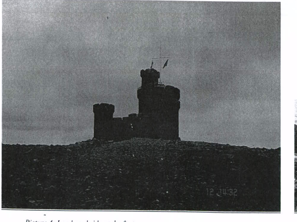
The Tower of Refuge is a stone structure built in 1832 as a shelter for shipwrecked sailors on Conister Rock in Douglas Bay. A solid triangular base with a single stepped entrance (facing towards land) is flanked by two small round turrets with a large round central tower that provides the refuge. There is a smaller higher square turret in the centre and a flag pole on top of the main tower. It is currently undergoing major restoration works by the Department of Transport to maintain its long term stability.
See Figure 1 Plan and Elevation of the Tower of Refuge on page 23
### Location
Approximately 500 m from shore, the Tower is clearly visible from Onchan head to Douglas Head, around the full length of Douglas Promenade and other higher properties behind. It is also on the approach to and from Douglas harbour which serves several passenger ferries a day and is often the first uniquely Manx point of interest seen by visitors.
See Figure 2 Location of the Tower of Refuge on page 24
### Environment
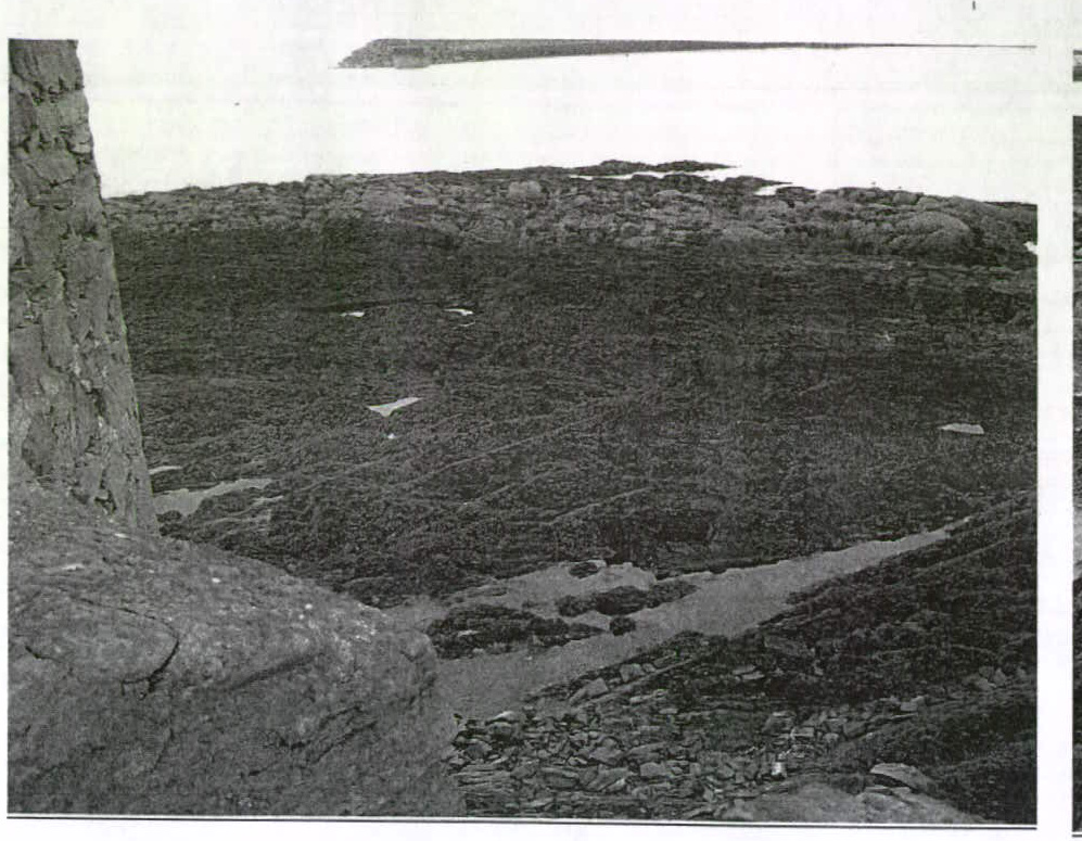
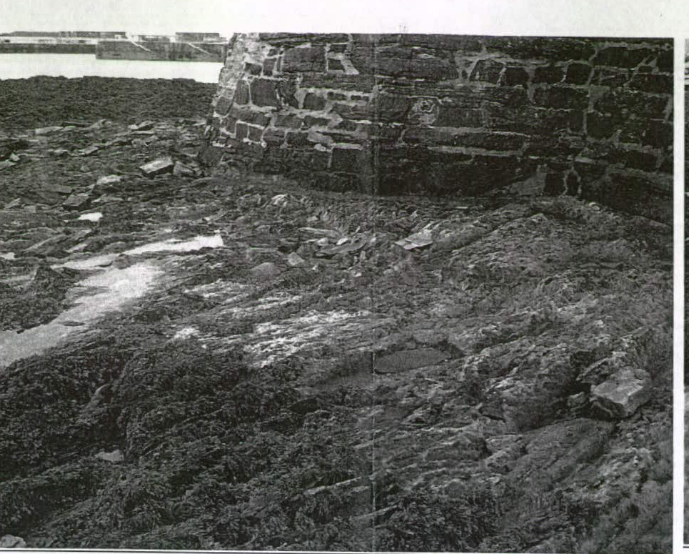
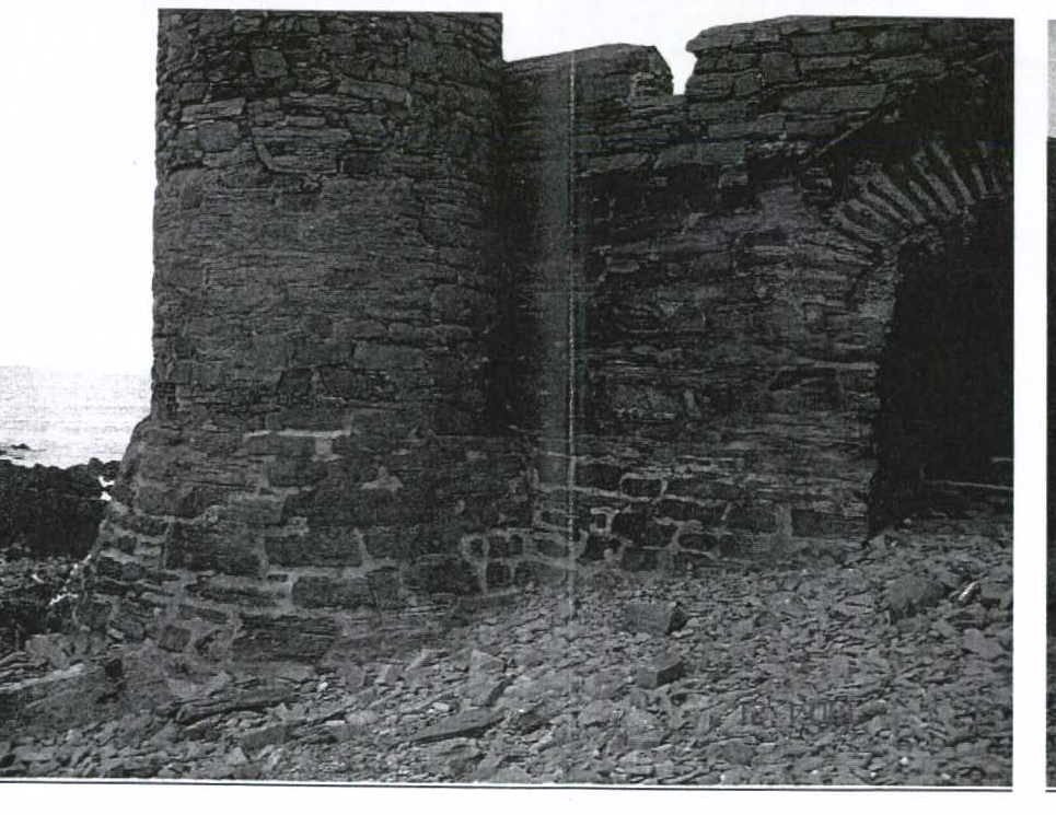
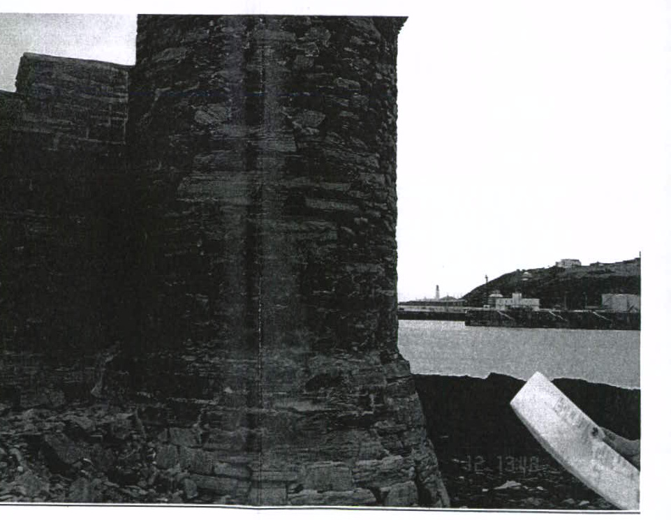
The Tower is situated in the harshest of marine environments with considerable exposure to tidal and storm conditions.
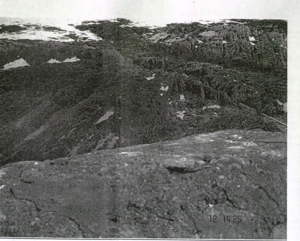
In the tidal region around the base of the tower, the seaward side is mostly bare rock with large vertical fissures and a covering of marine growth. The coastal side is a slope with large stones and debris covering the rock to varying degrees.
See Budget to Picture 6: Landward side rocks \& stones on page
## Accessibility
Almost all access to the Tower is via small boat, and the Department of Transport are renewing a jetty for better access as part of the structural renovation works. This restricts access quite considerably especially given the risks of rough seas and strong winds on the site.
In favourable conditions, suitable plant vehicles can access the site.
However, the site is occasionally accessible by foot, under favourable conditions of tide and weather, and therefore suitable precautions need to be considered.
### Consideration
In order to light the structure, the light source must be outside the building directed inwards. On a conventional monument or historic building this is location within a few metres of the base of the building shining upwards, this make the fitting readily accessible and enables the light to highlight the shapes and textures of the building masonry.
In this instance, any light fittings, and cables supplying them, mounted in this area would be extremely vulnerable to impact from wave borne debris or shifting stones and will be fully immersed at high water. It is likely that debris would accumulate on the fittings, especially after a storm. Therefore alternative locations and technologies will be assessed to find the most practical and cost effective solution.
### Lighting Position
In order to fully address the issue of locating the light fittings, it is necessary to investigate the light technology options available and evaluate the risks and costs.
Locate fully submersible lights one or two meters out from the base in the tidal zone
Although the technology exists for submersible flood lights, it is not suited to this case as the immersion is intermittent which would lead to heat build up and the risk of physical damage and debris covering the lights is very high.
See Appendix B: Marine Lighting for more details
Locate weatherproof lights at low level on the building above of the tidal zone
This seems to be the simplest method and is close to a conventional solution; however there are risks that need to be assessed. One is the fittings need to be at least 2 or 3 metres above the high tide level, this can be 4 or 5 metres above the surrounding ground, which is at best uneven and often slippery and leads to access problems for installation and maintenance. The second is the cables supplying the fittings need be on the outside of the building where they would be subject damage.
### Locate weatherproof lights at high level on the building directed downwards
This is a slightly unconventional method; however there are risks that need to be assessed. One is the fittings need to be at least 1 metre or more below the parapet on brackets. This would involve designing a safe means to pull up the bracket and fitting with cables to allow for safe maintenance and repair work on the inside of the tower. However, there is an added advantage that the cables supplying the fittings could be located internally and the fixings and brackets could be more sympathetic to the existing structure.
Locate powerful lights (light cannon/projectors) remotely on shore directed at tower
There exist very powerful ( ) lights that have special optics that can throw a very narrow bright beam of light over long distances ( ). However, they are expensive to buy, run and maintain and there are risks associated with the beam going off track near the harbour entrance. There are also issues with finding suitable sites to locate the fittings in a clean stable secure environment at the required locations.
See Appendix C: Remote Lighting for more details
## Summary
With due consideration for the workforce carrying out the installation and future maintenance of the lighting combined with the limited, but real, risk of members of the public accessing the site, an external low level scheme is impractical. The risks are especially high given the treacherous uneven nature of the ground around the tower from which any lighting would need to accessed and exposure of lights and associated wiring to the sea.
Weighing up all of the risks and costs, it was decided to develop the weatherproof lights at high level on the building directed downwards design option.
See Appendix K: Provisional Designer's Risk Assessment for more details
### Lighting Technology
Beyond the physical considerations of the design, there is the selection of lamp technology for quality and appearance of the light output and consequently the life expectancy of the lamp as well as installation, maintenance and operating cost.
### White LED flood light
One avenue of research was the relatively new technology of LED flood lighting. Although LED lighting has been around for several years, mostly as long life, low energy coloured applications such as displays or traffic lights, it is only in its infancy in high powered directional flood lights.
See Appendix F: LED Lighting for more details
### Metal Halide flood light
Metal halide lamps produce a very bright white light that is ideal for floodlighting large areas where colour of the surface being lit is important. This is especially important where the surface being lit has more than one colour of finish to pick out. For example, a band of coloured brick or contrasting window surrounds.
However, in this instance, the natural grey slate colour could leave the building looking monochrome or faded and the lighting designer felt a warmer, more yellow light, would be more effective.
Together with the fact that metal halide lamps have a lamp life of 6000 hours, which at 6 hours a day equates to 1,000 days ( 2.7 years) between lamp changes
In practice this would mean at least one, possibly two site visits a year to replace failed lamps with a complete re-lamping exercise every two years.
### SON flood light
High pressure sodium lights (White SON) are often used in roadway or car park lighting where the effect of the yellow tint on colour is of less importance than the efficiency of the light output. It also has the added benefit of a long lamp life of 30,000 hours at 6 hours a day equates to 5,000 days ( 13 years) between lamp changes.
In practice, this would mean at least one site visit a year to replace failed lamps, with a complete relamping exercise every ten years
The light fitting selected is referred to as Type B is a Thorn QBA fitting. See Appendix H: Type B Light for more details.
### Linear Fluorescent light
Apart from the shape and texture of the structure, one feature which can be highlighted is the projecting parapet around the turret tops and the three walls. Unlike the flood lighting approach this requires a type of light that can be wrapped around the tower or along the wall close in to just light the parapet. In this instance, a linear fluorescent light with suitable enclosure and optics has several advantages over any alternative.
This often used on buildings to highlight a linear feature such as a company name or sign, often raised lettering or symbols from close in and either above or below.
Mounted close to the wall and with a directional reflector, the light can be targeted onto the parapet and achieve a light level visible at a distance. One advantage of fluorescent lighting is that the lamps come in a range of colours from warm white (yellow tint) to cold white (blue tint) that will be chosen to work with the SON floodlights.
## Lighting Design
We employed the services of an architectural lighting specialist and furnished him with drawings, photographs and briefed him on our investigations and requirements with a view to him producing us a fully calculated lighting scheme with costs.
We visited site on 12th July 2007, where he took the opportunity to familiarise himself with both the environment and structure of the building.
We then received a full lighting design with costs and calculations to consider.
The design submitted consists of 68 No. linear fluorescent up lights (Type A/A1) to light the crown of the towers, in effect a continuous 'halo' around the top of the inner and outer walls and 30 No . downward floodlights (Type B) to light the majority of inner and outer walls.
### Initial analysis of the design
The full design includes for 99 No. light fittings at a cost of £ 20,470.50. Given a budget estimate for the remainder of the installation is £ 8,0000.00, the combined estimate of £ 28,470.50 exceeds the upper budget limit of £ 25,000 by some .
It was decided to reduce the scheme in two steps and do a cost comparison on each before making a recommendation on how to proceed.
### First reduction (Landside only)
The first cost reduction involved deciding which lights could be omitted on the basis that they simply would not be visible from land side and therefore not be missed by the vast majority of observers.. We requested and received a drawing from the client showing a viewing angle from Douglas Head to Onchan Head at the Tower of Refuge of (or on the seaward facing side). See Figure 4 Viewing angle sketch for Landside / Seaward Side Option on Page 26. This allowed us to omit 19 No. Type A fittings and 6 No. Type B fittings.
The landside only design includes for 68 No. light fittings at a cost of £ 13,809.84. Given a budget estimate for the remainder of the installations is £ 8,0000.00, the combined estimate of £ 21,809.84 was within the limits of £ 20,000 to £ 25,000 budget by some .
### Second reduction (Downward lights only)
The next cost reduction involved retaining the 31 No. Type downward floodlights 'as is' but completely remove the Type A/A1 linear fluorescent lights on the 'halo' altogether. The principle was to light around the whole tower ( ) but omit the 'halo' effect to reduce costs.
The downward lights only design includes for 31 No. light fittings at a cost of £ 6,166.54. Given a budget estimate for the remainder of the installation is £ 8,0000.00 which falls below the lower budget limit of £ 20,000 by .
### Recommended Design (Downward lights only)
The most cost effective and flexible option is to install the simplest system of 31 No. Type B lights with automatic controls and the energy saving equipment. The wiring system will have sufficient capacity and coverage to allow the expansion of the scheme to incorporate the addition of some or all of the Type A up lights at some future date.
The budget estimate for the installation works £ 17,500 with a contingency of giving a total budget estimate of £ 19,000. This is below the target of £ 20,000 to £ 25,000 requested by the client.
However, if the client was able to increase the budget to £ 30,000 and enable the full scheme to be installed in one go, we feel it would make more impact on a unique Manx landmark.
## Appendices
Appendix A: Submarine Cable
Appendix B: Marine Lighting
Appendix C: Remote Lighting
Appendix D: Renewable Energy Sources
Appendix E: Conventional Energy Sources
Appendix F: LED Lighting
Appendix G: Type A \& A1 Light
Appendix H: Type B Light
Appendix I: Budget Calculations
Appendix J: Energy Conservation
Appendix K: Provisional Designer's Risk Assessment
## Appendix A: Submarine Cable
On adoption of the Tower of Refuge, the Department of Transport inherited an existing submarine supply cable to the Tower from Douglas Corporation. A condition survey was requested and provided as follows;
Re: Electrical supply to the Tower of Refuge.
'The supply cable is either a 50 mm or 70 mm (more likely 70 mm ) S.W.A. marine grade, this cable was installed by approximately 20 men in either the late 1970's or early 1980's and is fed from a feeder pillar in the bottle neck car park area. This cable delivers a three phase supply under normal conditions. Unfortunately during the initial stages of the IRIS project the M.E.A. supply cable to the feeder pillar in the bottle neck car park area was damaged and was deemed too expensive to repair due to the fact that the car park was at that time only recently renewed. The damage caused one of the M.E.A.'s phases to be rendered non-operational thus providing only two working phase conductors, this presented no problem at the time as there was only the decorative lighting on the Tower of Refuge. At the present time there is no electrical apparatus on the Tower site itself with exception to a three phase mains board. The feeder pillar itself contains apparatus which would have to be renewed to conform to the latest IEE regulations. To reinstate the supply to three phase as opposed to its current form of two phase would require the renewing of the MEA supply cable to it's nearest junction or however they deem the best way and excavation of the car park. The cable has been insulation tested quite recently and was deemed completely fine and readings well within accepted limits. The supply current taking into consideration volt drop, ambient temperature and other factors is more than sufficient for any reasonable electrical scheme and more in depth calculations can be made to determine volt drop and current carrying capacities.'
Matthew Bawden - DoT Electrical Section
It is intended to reuse the existing cable to supply the new lighting scheme. Once the final design is established, it will include the necessary alterations and upgrades to meet the new load requirements. This will also include all electrical safety tests of the cable and installation.
## Appendix B: Marine Lighting
Fully submersible marine grade floodlights are often used in marinas, water features, and fish farms or diving. They are designed to be continuously immersed in water at depth, often tens of metres, and have powerful lamps .
When in use, the lamp and control creates heat, which must be dissipated to prevent the internal temperature exceeding operation limits. Over temperature will shorten lamp life dramatically and could heat air within the fitting which could expand and rupture the water seal.
However, as long as there is flow or volume of water around the fitting it can lose the heat into the surrounding water.
In the application proposed here, there would be insufficient submersion of the fitting to dissipate the heat as it would only be intermittently in the high water period.
For example see the attached data sheet for an Aqualux Black Satin, which refers to this issue;
'Lamps must be fully immersed during operations. Water level switches are available for inclusion within power supplies and control circuits to ensure that a minimum of 50 mm ( 2 inches) of water is maintained above the lamps.'
A final consideration is the effect of waves and submersion on the light from the lamp on to the structure. Unless the fittings were all mounted at the same level and submerged to the same depth, their light output could be very uneven and patchy creating a very poor overall lighting effect on the building.
## Appendix C: Remote Lighting
One approach given early consideration was a long distance projector or 'light cannon', which gives a very powerful and narrow beam of light to illuminate objects at a distance. Using at least two units at very different locations, these would be mounted on shore and aimed directly at the tower from different angles to illuminate both sides visible from land. The seaward side couldn't be lit this way as there would be no stable place to mount a light there.
A light cannon consists of a very powerful light source, some Xenon 4000 W or more, together with some very sophisticated optics to focus the light. Together with fans to cool the lamp and controls, these fittings can be up to 2 meters long and weigh at least 150 kilogram's with prices in the £ 10,000 range. 4000 W xenon lamps cost £ 500 each and only have a lamp life of .
Given an estimated daily operational time of 6 hours, at lamp life, the lamps could last as little as 100 days or 3 months. If there were 2 No. projector's, this could be a lamp change every 6 weeks ( changes =£ 4500 per annum in lamps alone)
On electricity consumption at 6 hours for 7 days a week at 8 kW gives 336 kWh a week at =£ 43.68 a week or £ 2271.36 per annum to run.
Given a beam angle of less than 3 degrees, (see Figure 3 Beam angle sketch for Light Cannon ) mounting would have to be very secure or well shielded to avoid the beam straying offline and dazzling harbour users by accident.
Finally, there my be issues surrounding the use of these lights during periods of heavy fog or sea mist at night if it interfered with either shipping or harbour controls view of the harbour entrance area.
### Appendix D: Renewable Energy Sources
[Table omitted in markdown export]
Table 1 Renewable energy sources
## Appendix E: Conventional Energy Sources
| Conventional Energy | Negative aspects | Positive aspects |
| :--: | :--: | :--: |
| Diesel Generator - A diesel engine drives a generator usually combined within a containerised package, which includes a base fuel tank and controls. | - High installation cost
- Fuel storage and subsequent risk to environment
- Access to refuel.
- Need for supply to charge batteries and pre-heaters.
- Ongoing maintenance of engine and generator.
- Exhaust smoke and noise
- Risk of damage. | - Supply available on demand
- Proven technology |
| Submarine cable - A cable laid from the site to land across the seabed. | - High installation cost
- Risk of damage. | - Supply available on demand
- Proven technology
- Already in use |
Table 2 Conventional energy sources
## Appendix F: LED Lighting
There are several major benefits to LED lighting that would be of benefit to this installation. The first is lamp life; a conventional metal halide lamp has an average life of 6000 hours ( 250 days) whereas LED lamps are 50,000 hours. (2,083.3 days) Secondly, LED floodlights are an array of 20-30 individual lamps so that even the loss of 4 or 5 lamps per fitting would have less impact upon the overall illumination than a single conventional lamp failure which would leave sections without illumination. Thirdly, Fourthly, LED lamps can be readily controlled to dim and change colour without filters,
A sample fitting was organised for evaluation and demonstrated that the technology is capable of achieving the necessary light levels and colour. In fact the sample fitting had a built in controller that allowed simple colour changing and dimming sequences by selecting functions through an integral display and keypad.
We were given a budget estimate of between £ 1,000.00 and £ 1,200.00 per fitting. For comparison, a conventional fitting is in the order of £ 200 per fitting. At present it was felt that although LED technology has many advantages there is a premium to pay. There is also a risk that the technology is relatively new and somewhat unproven. However, it would be worth a new assessment in 5 or 6 years time when the technology would be cheaper and proven.
## Corniche
## 96010453 Corniche 39W T16/Li/860 E/Pc A/S
G5 39W T16
IK10
IP65
## Thorn
Slim linear T16 luminaire providing 'close off-set' façade illumination with good uniformity A slim linear T5 luminaire with IP65 optical and gear compartment, Electrical Class II. asymmetrical distribution. powder coated extruded aluminium body with clear polycarbonate enclosure. Projector supplied with two versatile brackets which can slide along the length of the extrusion.
aluminium - bright anodised optics with 39W T16 lamp providing a broad band of even illumination on a surface from a close mounting position.
Suitable for uplighting and downlighting installations.
Dimensions: 917 x 140 x 158 mm
Weight: 4.6 kg
TLG_CRNC_F_CO.jpg
TLG_CRNC_M_LD1.wmf
TLG_LA_CTSAKBCF.ldt
Lamp position: STD - standard
Lamp: T16 39W
LOR: 0,90 ULOR: 0,00 DLOR: 0,90
## Appendix H: Type B Light
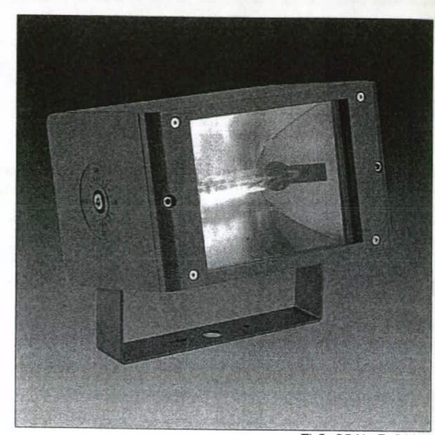
### Qba
### 96012220 Qba 2150 W 240V HIT-HST-DE A/S
### Qba
A compact discharge floodlight for architectural lighting with IP65 optical and gear compartment, SC1 class. Grey powder coated die-cast aluminium body with Flat Glass enclosure.
Projector is fully adjustable on a short stirrup, locked via central 8 mm diameter allen screws.
asymmetrical floodlighting distribution with a aluminium texturebrite reflector.
This product is suitable for a 150 W HST-DE/HIT-CE-DE lamp.
Available in other colours as special (any RAL number, brick brown or pale sand).
Dimensions :
Weight: 6.29 kg
TLG_QBAL_M_LD1.wmf
TLG_QBAL_F_S1.jpg
Lamp position:STD - standard
Lamp:HST-DE/HIT-CE-DE 150W
## Appendix I: Budget Calculations
Note: Running costs are calculated @ and an operational time of 6 hours per day 365 days a year or -year except the controls and heating which are assumed to be 24 hours per day 365 a year or -year. There is also a daily standing charge of 13.15 p per day or £ 48.00 / year.
### Common elements
### Field Wiring
20 No. IP68 6-way connection boxes
@ £ 34.75
£ 695.00
20 No. Male IP 68 plugs
@ £ 6.49
£ 129.80
20 No. Female IP 68 plugs
@ £ 6.49
£ 129.80
200 m H07RN-F Neoprene cable
@
£ 590.00
£ 1544.60
### Controls
1 No. IP68 6-way distribution board
£ 315.00
Including 1 No. SPN 16A RCBO (Socket)
£ 75.00
1 No. SPN 16A MCB (Heater)
£ 45.00
1 No. SPN 6A MCB (Control Circuit)
£ 45.00
1 No. TPN 16A MCB (Lights)
£ 60.00
1 No. TPN 20A Contactor (Lights)
£ 115.00
1 No. TPN 125A Isolator
£ 40.00
£ 695.00
1 No. 100W tubular heater
£ 230.00
1 No. Time switch (24hr 7 day daylight)
£ 150.00
1 No. IP65 Maintenance socket
£ 50.00
£ 430.00
Energy Conservation
1 No. 20A 3 phase Econo-Miser
£ 875.00
### MEA works
Repair cable below car park
£ 500.00
### Labour
90 Hours labour (@£25/h)
£2,250.00
Sub-Total
### Running Costs
0.2 kW @ -year
£ 218.00
Standing charge
£ 48.00
Total
£ 266.00
### Full Scheme
### Light fittings
64 No. Type A upward lights
@ £ 210.27 £ 13,457.28
4 No. Type A1 upward lights
@ £ 211.52 £ 846.08
31 No. Type B downward floodlights (inc. 150W lamp each)
@ £ 198.94 £ 6,166.54
99 No. IP68 5m leads
@
### Labour
90 Hours labour @£25/h
£ 2250.00
**Sub-Total = £21,125.28**
**Running Costs per year**
7.2kW @ £272/kW-year
£ 1,958.40
Standing charge
£ 48.00
Total
£ 2,006.40
### Landside Only Scheme
#### Light fittings
45 No. Type A upward lights @£210.27 £ 9,462.15
4 No. Type A1 upward lights @£211.52 £ 846.08
25 No. Type B downward floodlights (inc. 150W lamp each) @£198.94 £ 4,474.75
74 No. IP68 5m leads @£ 6.62 £ 489.88
#### Labour
67 Hours labour @£25/h
£ 1675.00
**Sub-Total = £16,974.86**
**Running Costs**
5.6kW @ £272/kW-year
£ 1,523.20
Standing charge
£ 48.00
Total
£ 1,571.20
### Downward Light Only Scheme
#### Light fittings
31 No. Type B downward floodlights (inc. 150W lamp each) @£198.94 £ 5,548.69
31 No. IP68 5m leads @£ 6.62 £ 205.22
#### Labour
31 Hours labour @£25/h
£ 775.00
**Sub-Total = £6,528.91**
**Running Costs**
4.65kW @ £272/kW-year
£ 1,264.80
Standing charge
£ 48.00
Total
£ 1,312.80
### Summary
**Table 3 Summary of Budget Costs**
† This does not include the builders work element of supplying and fitting mounting brackets
* This does not include Economiser savings. See Appendix J: Energy Conservation
18/27
[Table omitted in markdown export]
## Appendix J: Energy Conservation
The economiser is a device which reduces the input voltage to discharge lighting Type B fittings, without decrease in light output; this reduces both the running costs and extends the lamp life. However, as linear fluorescents of the A Type fittings already have this built into their controls it has no added benefit for them.
As the Economiser only works on the Type B luminaires, saving 20-25\% energy costs, the following payback periods have been calculated.
Full Scheme: Type B running costs -year =£ 1264.80
Payback on £ 875.00=3.4 years
Landward side only: Type B running costs -year =£ 1020.00
Payback on £ 875.00=4.3 years
Down light only: Type B running costs -year =£ 1264.80
Payback on £ 875.00=3.4 years
Appendix K: Provisional Designer's Risk Assessment
Key:
L = Likelihood (Low, Medium, High)
S = Severity (Low, Medium, High)
R = Risk (Low, Medium, High)
[Table omitted in markdown export]
Key:
L = Likelihood (Low, Medium, High)
S = Severity (Low, Medium, High)
R = Risk (Likelihood X Severity)
21/27
[Table omitted in markdown export]
Key:
L = Likelihood (Low, Medium, High)
S = Severity (Low, Medium, High)
R = Risk (Likelihood X Severity)
22/27
[Table omitted in markdown export]
Figure 1 Plan and Elevation of the Tower of Belage
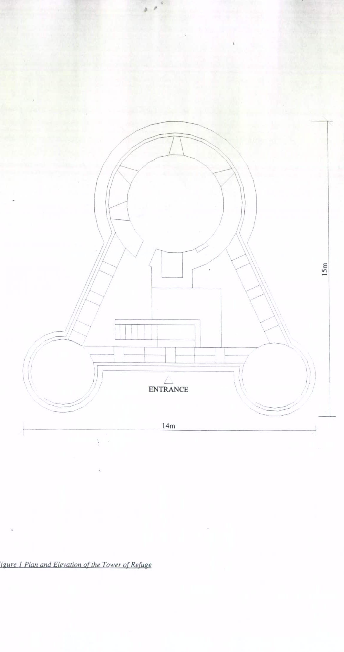
Figure 2 Location of the Tower of Refuge
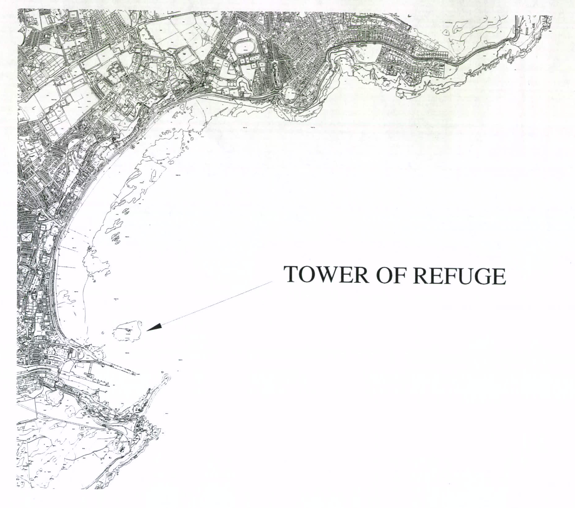
Figure 3 Beam angle sketch for Light Cannon
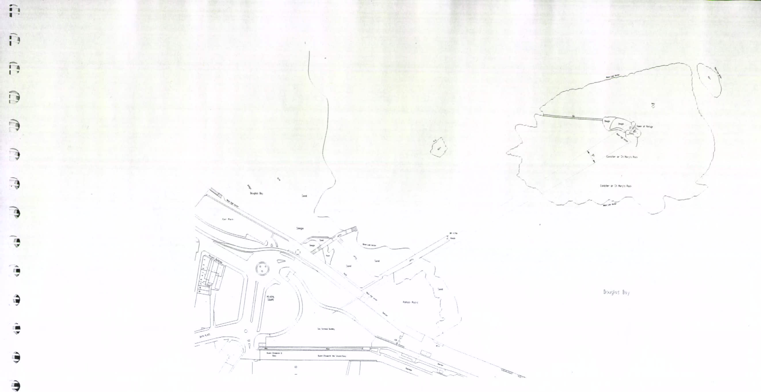
Figure 4 Viewing angle sketch for Landside / Seaward Side Option
Picture 1: Seaward side rocks \& pools
Picture 4: Landward side rocks \& stones
Picture 2: Seaward side rocks \& pools
Picture 5: Landward side rocks \& stones
Picture 3: Seaward side rocks \& pools
Picture 6: Landward side rocks \& stones
---
*Data sourced from the Isle of Man public planning register under the [Isle of Man Open Government Licence](https://www.gov.im/about-this-site/open-government-licence/).*
*Canonical page: https://planningportal.im/a/63623-braddan-tower-of-refuge-st-marys-replacement/documents/1570518*